
SmartSwitch
TM
AAT4644
4-Channel Current Limited Load Switch
Preliminary
Information
4644.2002.01.0.92
1
General Description
The AAT4644 is a four-channel resettable fuse. It
utilizes independent current-limited and thermally
protected P-channel MOSFETs to protect against
short circuits. Each switch's current limit is factory
programmed at 1A. Additional protection is provid-
ed with undervoltage lockout; the switches are
turned off when the input voltage drops below a
preset level. The quiescent supply current is typi-
cally 20µA. The AAT4644 is a flexible solution,
allowing system designers to gang outputs togeth-
er for lower R
DS(ON)
and higher current limit.
The AAT4644 is available in 8 pin TSSOP or SOP
packages, specified over -40 to 85∞C.
Features
∑
500mA per channel steady state
∑
4 X 1A current limit trip point
∑
Over-temp protection
∑
Fast transient response:
∑
1µs (typ) response to short circuit
∑
100m
typical R
DS(ON)
∑
Undervoltage Lockout
∑
Temp range -40 to 85∞C
∑
8 pin TSSOP or SOP packages
Applications
∑
USB ports
∑
Peripheral ports
∑
Desktop PCs
Typical Application
AAT4644
2,7
1
3
8
6
4
IN
INPUT
3.3V - 5V
GND
OUT1
OUT2
OUT3
OUT4
OUTPUT1
OUTPUT2
OUTPUT3
OUTPUT4

Pin Descriptions
Pin Configuration
SO-8
TSSOP-8
(Top View)
(Top View)
1
2
IN
OUT3
OUT4
NC
OUT1
IN
OUT2
GND
1
2
3
4
8
7
6
5
1
2
OUT1
IN
GND
OUT2
OUT3
IN
OUT4
NC
Pin #
Symbol
Function
1
OUT1
Channel 1 output
2, 7
IN
These pins are the input supply to the circuit
3
OUT2
Channel 2 output
4
GND
Ground connection
5
NC
Not internally connected
6
OUT4
Channel 4 output
8
OUT3
Channel 3 output
AAT4644
4-Channel Current Limited Load Switch
2
4644.2002.01.0.92

AAT4644
4-Channel Current Limited Load Switch
4644.2002.01.0.92
3
Absolute Maximum Ratings
(T
A
=25∞C unless otherwise noted)
Note: Stresses above those listed in Absolute Maximum Ratings may cause permanent damage to the device. Functional operation at con-
ditions other than the operating conditions specified is not implied. Only one Absolute Maximum rating should be applied at any one time.
Note 1: Human body model is a 100pF capacitor discharged through a 1.5k
resistor into each pin.
Thermal Characteristics
Note 2: Mounted on a demo board.
Electrical Characteristics
(V
IN
= 5V, T
A
= -40 to 85∞C unless otherwise noted. Typical values
are at T
A
=25∞C;
bold values designate full temperature range)
Symbol
Description
Conditions
Min
Typ
Max
Units
V
IN
Operation Voltage
2.7
5.5
V
I
Q
Quiescent Current
Vin = 5V, Iout = 0
20
40
µA
V
UVLO
Undervoltage Lockout
Rising edge
1.75
V
V
UVLO(hys)
Undervoltage Lockout Hysteresis
0.3
V
R
DS(ON)
On-Resistance
Vin=5.0V,T
A
= 25∞C
100
125
m
I
LIM
Current Limit
Each output OUT<IN -1V
0.6
1.0
1.5
A
t
RESP
Current Loop Response
Vin=5V
1
µs
T
SD
Over-temperature threshold
125
∞C
Symbol
Description
Value
Units
JA
Maximum Thermal Resistance
100
∞C/W
P
D
Maximum Power Dissipation
1.25
W
Symbol
Description
Value
Units
V
IN
IN to GND
-0.3 to 6
V
V
OUT
OUT to GND
-0.3 to 6
V
I
OUT
Output Current
Internally Limited
A
T
J
Operating Junction Temperature Range
-40 to 85
∞C
V
ESD
ESD Rating
1
--HBM
4000
V
T
LEAD
Maximum Soldering Temperature (at Leads)
300
∞C
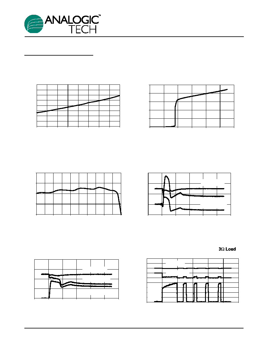
Typical Characteristics
(T
A
= 25∞C unless otherwise noted)
Thermal Shutdown Response 0.
-100
0
100
200
300
400
500
Vout (5A/div)
Vin(5v/div)
Iout
(500mA /
div)
Time (
µ
s)
Short Circuit Through 0.6 Ohm
0
2
4
6
8
-1
0
1
2
3
4
5
Input and Output (V)
Output (A)
0
2
4
6
8
Input Voltage
Output Current
Output Voltage
Time (
µ
s)
Short Circuit Through 0.3 Ohm
0
2
4
6
8
-1
0
1
2
3
4
5
Input and Output (V)
Output (A)
-4
0
4
8
12
Input Voltage
Output Voltage
Output Current
Time (
µ
s)
Current Limit
0
0.5
1
1.5
2
0
1
2
3
4
5
O
Output (A)
utput (V)
Quiescent Current
0
5
10
15
20
25
0
1
2
3
4
5
6
Input (V)
Input (
µ
A)
Quiescent Current vs. Temperature
0
5
10
15
20
25
30
35
40
-40
-20
0
20
40
60
80
100
120
Temperature (
∞
C)
Quiescent Current (
µ
A)
AAT4644
4-Channel Current Limited Load Switch
4
4644.2002.01.0.92

AAT4644
4-Channel Current Limited Load Switch
4644.2002.01.0.92
5
(T
A
= 25∞C unless otherwise noted)
Block Diagram
GND
IN
OUT1
OUT2
OUT3
OUT4
Channel 4 Control
Current Limit, Over-temp
Undervoltage
Lockout
Channel 3 Control
Current Limit, Over-temp
Channel 2 Control
Current Limit, Over-temp
Channel 1 Control
Current Limit, Over-temp
Rdson vs. Temperature
70.0
80.0
90.0
100.0
110.0
120.0
130.0
140.0
150.0
-40
-20
0
20
40
60
80
100
120
Te
Rdson (m
)
mperature (
∞
C)
V
IN
=3V
V
IN
=5V

AAT4644
4-Channel Current Limited Load Switch
6
4644.2002.01.0.92
Ordering Information
Package Information
SOP-8
E
b
e
H
D
A1
A
A2
7 (4x)
c
L
y
Q
Package
Marking
Part Number
Bulk
Tape and Reel
SOP8
AAT4644IAS-B1
AAT4644IAS-T1
TSSOP8
AAT4644IHS-B1
AAT4644IHS-T1
Dim
Millimeters
Inches
Min
Max
Min
Max
A
1.35
1.75
0.053
0.069
A1
0.10
0.25
0.004
0.010
A2
1.45
0.057
B
0.33
0.51
0.013
0.020
C
0.19
0.25
0.007
0.010
D
4.80
5.00
0.189
0.197
E
3.80
4.00
0.150
0.157
e
1.27
0.050
H
5.80
6.20
0.228
0.244
L
0.40
1.27
0.016
0.050
Y
0.00
0.10
0.000
0.004
1
0∞
8∞
0∞
8∞
Note:
1. PACKAGE BODY SIZES EXCLUDE MOLD FLASH
PROTRUSIONS OR GATE BURRS.
2. TOLERANCE 0.1000mm (4mil) UNLESS
OTHERWISE SPECIFIED
3. COPLANARITY: 0.1000mm
4. DIMENSION L IS MEASURED IN GAGE PLANE.
5. CONTROLLING DIMENSION IS MILLIMETER;
CONVERTED INCH DIMENSIONS ARE NOT
NECESSARILY EXACT.

TSSOP-8
A1
b
e
E
1 2
A
A2
E1
DETAIL A
R
L1
L
0.20
D
R1
2
E
1
DETAIL A
AAT4644
4-Channel Current Limited Load Switch
4644.2002.01.0.92
7
Dim
Millimeters
Inches
Min
Max
Min
Max
A
1.05
1.20
0.041
0.047
A1
0.05
0.15
0.002
0.006
A2
-
1.05
-
0.041
b
0.25
0.30
0.010
0.012
c
0.127
0.005
D-8
2.90
3.10
0.114
0.122
D-28
9.60
9.80
0.378
0.386
E
4.30
4.50
0.170
0.177
E1
6.20
6.60
0.244
0.260
e
0.65 BSC
0.025 BSC
L
0.50
0.70
0.20
0.028
L1
1.0
0.039
R
0.09
-
0.004
-
R1
0.09
-
0.004
-
1
0∞
8∞
0∞
8∞
2
12∞

This page intentionally left blank.
AAT4644
4-Channel Current Limited Load Switch
8
4644.2002.01.0.92
Advanced Analogic Technologies, Inc.
1250 Oakmead Parkway, Suite 310, Sunnyvale, CA 94086
Phone (408) 524-9684
Fax (408) 524-9689