Available on Tape
and Reel For Pick and
Place Manufacturing.
USA/Canada:
Toll Free:
Europe
:
(315) 432-8909
(800) 544-2414
+44 2392-232392
Model D10AAXXZ1
Features:
∑
10 Watts
∑
Lowest Cost
∑
True Surface Mount
∑
Alumina Ceramic
∑
Non-Nichrome Resistive
Element
∑
Low VSWR
∑
100% Tested
Surface Mount Attenuator
10 Watts
Description
The D10AAXXZ1 is high performance Alumina (Al2O3) surface mount
attenuator intended as a lower cost alternative to Aluminum Nitride (AlN)
and Beryllium Oxide (BeO). The attenuator is well suited to all cellular
frequency bands such as; AMPS, GSM, DCS, PCS, PHS and UMTS. The
high power handling makes the part ideal for inter-stage matching,
directional couplers, and for use in isolators.
General Specifications
Resistive Element
Thick film
Substrate
Alumina Ceramic
Terminal Finish
Thick film Silver
Operating Temperature
-55 to +125
∞
C (see chart)
Tolerance is
±
0.010", unless otherwise specified. Designed to meet of exceed
applicable portions of MIL-E-5400. All dimensions in inches.
Electrical Specifications
Attenuation Value:
1 ≠ 6, 9, 10, 20 & 30dB
Power:
10 Watts
Frequency Range:
DC ≠ 3.0 GHz
V.S.W.R.:
<1.25:1
Specification based on unit properly installed using suggested mounting instructions
and a 50 ohm nominal impedance. Specifications subject to change.
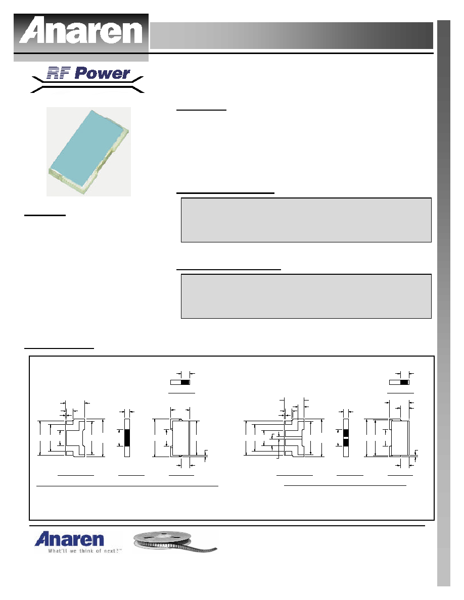
Outline Drawing
.100
REF.
.035
.182
.140 .080
.005
BOTTOM VIEW
.200
A
C
.175
.200
REF.
B
D
.025
SIDE VIEW
.090
REF.
.045
REF.
.182
.045
.009
.100
XX
TOP VIEW
.090
SIDE VIEW
BOTTOM VIEW
.035
.100
REF.
.005
.140
B
A
.080
.090
.200 .190
.090
REF.
SIDE VIEW
.025
.200
REF.
D
.175
C
.100
.009
TOP VIEW
.045
.045
XX
SIDE VIEW
.045
REF.
FOR PART NUMBERS D10AA20Z1 AND D10AA30Z1
FOR PART NUMBERS D10AA1Z1 TO D10AA6Z1, D10AA9Z1 AND D10AA10Z1
.035
.182
.010
.030
Dimensions given in inches.
Rev. 11/07/03
USA/Canada:
Toll Free:
Europe:
(315) 432-8909
(800) 544-2414
+44 2392-232392
Available on Tape and
Reel For Pick and Place
Manufacturing.
Model D10AAXXZ1
Specifications:
PART NUMBER
ATTENUATION(dB)
TOL. (±dB)
POWER (WATTS)
VSWR
FREQ (GHZ)
D10AA1Z1
1
0.30
10
1.25:1
3.0
D10AA2Z1
2
0.30
10
1.25:1
3.0
D10AA3Z1
3
0.30
10
1.25:1
3.0
D10AA4Z1
4
0.30
10
1.25:1
3.0
D10AA5Z1
5
0.30
10
1.25:1
3.0
D10AA6Z1
6
0.30
10
1.25:1
3.0
D10AA9Z1
9
0.25
10
1.25:1
3.0
D10AA10Z1
10
0.25
10
1.25:1
3.0
D10AA20Z1
20
0.50
10
1.25:1
2.5
D10AA30Z1
30
1.00
10
1.25:1
2.0
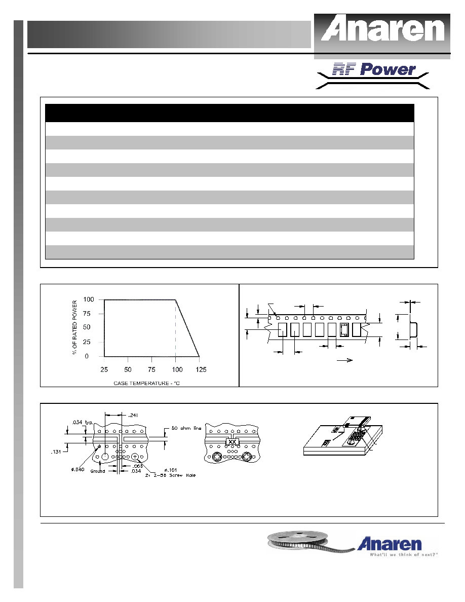
Power De-rating:
Tape & Reel:
.160
.160
.120
.070
.215
.010
.070
.220
.470
DESPOOLING DIRECTION
.060
DIA.
XX
Dimension given in inches.
Mounting Footprint and Procedure:
Dimension given in inches.
For best thermal performance the PCB should be placed with thermal joint compound to
the heat sink.
FILLED VIA
SCREW
(2 PLS.)
SOLDER
1. Drill thermal vias through PCB and fill with solder, such as SN63 type.
2. Solder part in place using SN63 type solder with controlled temperature iron
(700∞F).
3. To ensure good thermal connectivity to heat sink, drill and tap heatsink and mount
PCB board to heat sink using screws.
MOUNTING PROCEDURE
HEATSINK
SOLDER
PASTE
PC BOARD
SOLDER
PASTE