Aluminum Nitride Attenuators
100 Watts
Model RFP-100NXXAE
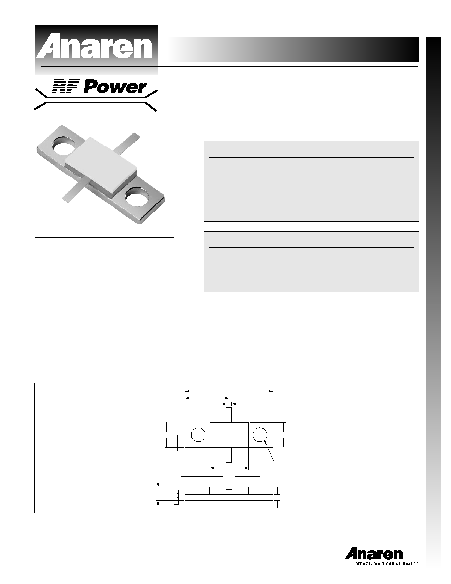
Outline Drawing
.399
.798
.115
.230
.119
.560
.350
.050
TYP
.060
.125
.100
.130 DIA. THRU
(2 PLACES)
.225
100NXX
RFP
AE
Aluminum Nitride Flanged Attenuators
1
Sales Desk USA: Voice: (800) 544-2414 Fax: (315) 432-9121
Sales Desk Europe: Voice: (+44) 23 92 232392 Fax: (+44) 23 92 251369
Features
∑ DC ≠ 2.5 GHz
∑ 100 Watts
∑ Aluminum Nitride (AIN) Ceramic
∑ Welded Silver Leads
∑ Non-Nichrome Resistive
Element
∑ Low VSWR
∑ 100% Tested
Notes: Tolerance is ±.010, unless otherwise specified. Operating
temperature is -55∞C to +150∞C (see chart). Designed to meet or exceed
applicable portions of MIL-E-5400. All dimensions are in inches. Lead
length 0.15" minimum.
Specifications subject to change without notice.
Electrical Specifications
Attenuation Value:
1, 2, 3, 4, 5, 6, 9, 10, 20 or
30db
Frequency Range:
DC - 2.5 GHz
Power:
100 Watts
General Specifications
Resistive Element:
Thick film
Substrate:
Aluminum nitride ceramic
Cover:
Alumina ceramic
Mounting Flange:
Copper nickel plated per
QQ-N-290
Lead(s):
99.99% pure silver (.005" thk)
Note: XX denotes attenuation value.
VER. 12/5/01
Aluminum Nitride Flanged Attenuators
Model RFP-100NXXAE
2
Sales Desk USA: Voice: (800) 544-2414 Fax: (315) 432-9121
Sales Desk Europe: Voice: (+44) 23 92 232392 Fax: (+44) 23 92 251369
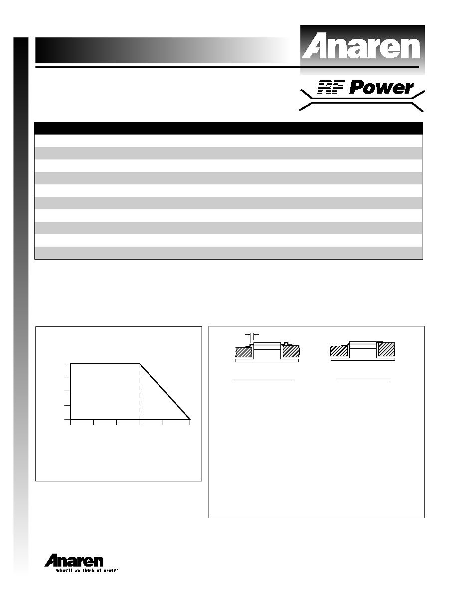
Power Derating
Suggested Mounting Procedures
SUGGESTED STRESS RELIEF METHODS
SCALE: NONE
BOARD LOWER
THAN LEAD.
.025
(2 PLACES)
MIN.
WITH LEAD.
BOARD EVEN
1. Make sure that the devices are mounted on flat surfaces
(.001" under the device) to optimize the heat transfer.
2. Drill & tap the heatsink for the appropriate thread size to be
used
3. Coat heatsink with a minimum amount of high quality
silicone grease (.001" max. thickness).
4. Position device on mounting surface and secure using
socket head screws, flat & split washers. Torque screws to
the appropriate value. Make sure that the device is flat
against the heatsink. (Care should be taken to avoid
upward pressure of the leads towards the lid).
3. Solder leads in place using an SN63 type solder with a
controlled temperature iron (210∞C)
CASE TEMPERATURE --
∞C
% OF RATED POWER
150
125
100
75
50
25
100
75
25
50
0
Specifications
PART NUMBER
ATTENUATION (dB)
TOL. (+/-dB)
POWER (WATTS)
VSWR
FREQ. (GHZ)
RFP-100N1AE
1
0.2
100
1.25:1
2.5
RFP-100N2AE
2
0.4
100
1.25:1
2.5
RFP-100N3AE
3
0.4
100
1.25:1
2.5
RFP-100N4AE
4
0.4
100
1.25:1
2.5
RFP-100N5AE
5
0.4
100
1.25:1
2.5
RFP-100N6AE
6
0.4
100
1.25:1
2.5
RFP-100N9AE
9
0.5
100
1.25:1
2.5
RFP-100N10AE
10
0.5
100
1.25:1
2.5
RFP-100N20AE
20
0.5
100
1.25:1
2.5
RFP-100N30AE
30
1.0
100
1.25:1
2.5
THAN LEAD.
BOARD LOWER
NOT RECOMMENDED APPLICATION
SCALE: NONE
BOARD HIGHER
THAN LEAD.