
Available on Tape
and Reel For Pick and
Place Manufacturing.
USA/Canada:
Toll Free:
Europe
:
(315) 432-8909
(800) 544-2414
+44 2392-232392
Model RFP-1500-XX-50
Features:
∑
100 Watts
∑
Lowest Cost
∑
True Surface Mount
∑
Xinger
©
Circulator Matched
∑
Alumina Ceramic
∑
Non-Nichrome Resistive
Element
∑
Low VSWR
∑
100% Tested
Surface Mount Termination
100 Watts, 50
Description
The RFP-1500-XX-50 family of surface mount terminations consists of
five parts matched to the complex impedance of each of the five high
power Xinger circulators. With each termination matched to the
circulator's complex impedance, the pair will provide superior
performance and a true pick and place solution. The SMD terminations
are available for AMPS, GSM, DCS, PCS and UMTS frequency bands,
and they can be used in many applications, not only as the load on the
Xinger circulator. Other typical applications include the termination for the
isolated port of 3dB couplers.
General Specifications
Resistive Element
Thick film
Substrate
Alumina
Terminal Finish
Thick film Silver
Operating Temperature
-55 to +125
∞
C (see chart)
Tolerance is
±
0.010", unless otherwise specified. Designed to meet of exceed
applicable portions of MIL-E-5400. All dimensions in inches.
Electrical Specifications
Resistance Value:
50 ohms,
±
2%
Power:
100 Watts
(with PCB solder down to heatsink)
Frequency Range:
896-894, 925-960, 1805-1880, 1930-
1990, 2110-2170 MHz
V.S.W.R.:
<1.15:1
Specification based on unit properly installed using suggested mounting instructions
and a 50 ohm nominal impedance. Specifications subject to change without notice
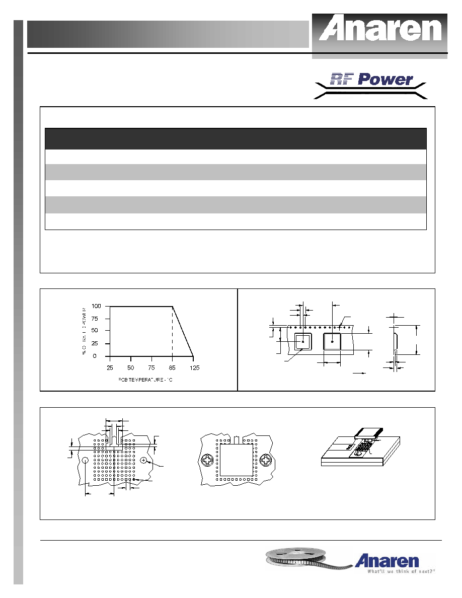
Outline Drawing
SIDE VIEW
TOP VIEW
BACK VIEW
.060 [1.52]
.500 [12.70]
.500 [12.70]
.182 [4.64]
.135 [3.43]
.040 [1.02]
.100 [2.54]
POINT IN WHICH
TEMP. IS MEASURED
HATCHED AREA INDICATES
LOCATION OF PROTECTIVE
GLASS COATING
.063 [1.61] (2X)
.060 [1.53] (2X)
ÿ.118 [ÿ3.00]
(2X)
ÿ.474 [ÿ12.03]
.200 [5.08]
CL
RFP
1500-XX-50
DIMENSIONS IN INCHES [MILLIMETERS]
XX DENOTES CIRCULATOR TYPE
Rev. 10/ 24/03
USA/Canada:
Toll Free:
Europe:
(315) 432-8909
(800) 544-2414
+44 2392-232392
Available on Tape and
Reel For Pick and Place
Manufacturing.
Model RFP-1500-XX-50
Typical Performance:
Part Number
Resistance (ohms)
Tol. (+/-)
VSWR
Frequency
(MHz.)
Matched Circulator
RFP-1500-8-50
50
2.0
1.15:1
869-894
X800x-100
RFP-1500-9-50
50
2.0
1.15:1
925-960
X900x-100
RFP-1500-18-50
50
2.0
1.15:1
1805-1880
X180x-100
RFP-1500-19-50
50
2.0
1.15:1
1930-1990
X190x-100
RFP-1500-21-50
50
2.0
1.15:1
2110-2170
X210x-100
Note: X800x-100, where x refers to the circulator direction of rotation: L for clockwise or R for counter
clockwise rotation, i.e. X800R-100.
Power De-rating:
Tape & Reel:
INPUT PAD
.453 [11.51]
.069 [1.75]
DIMENSION IN INCHES [MILLIMETERS]
.012 [0.30]
.062 [1.58]
.106 [2.69]
DESPOOLING DIRECTION
.945 [24.01]
.535 [13.60]
RFP
.079 [2.01]
.164 [4.18]
ÿ.059 [ÿ1.50]
.535 [13.60]
PART NUMBER
.945 [24.01]
Mounting Footprint and Procedure:
1500-XX-50
50 ohm Transmission Line
Dimensions are in Inches [Millimeters]
RFP
0.135 [3.43]
0.040 [1.02]
0.060 [1.52]
0.255 [6.48]
0.060 [1.52]
ÿ0.031 [ÿ0.79]
0.450 [11.43]
ÿ0.101 [ÿ2.57]
2x 4-40 Screw Hole
1. Drill thermal vias through PCB and fill with solder, such as SN63 type.
2. Solder part in place using SN63 type solder with controlled temperature iron
(700∞F).
3. To ensure good thermal connectivity to heat sink, which is critical for proper
operation drill and tap heatsink and mount PCB board to heat sink using screws.
SOLDER
FILLED VIA
SOLDER
PASTE
HEATSINK
MOUNTING PROCEDURE
PC BOARD
(2 PLS.)
SCREW