Aluminum Nitride Terminations
200 Watts, 50
Model RFP-375375N6X50-2
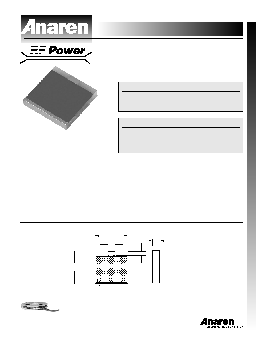
Outline Drawing
ALN
375375
6Xxxx
HATCHED AREA INDICATES
LOCATION OF PROTECTIVE COATING
.045
.080
.375
.375
TOP VIEW
SIDE VIEW
.060
Aluminum Nitride Chip T
e
rminations
1
Sales Desk USA: Voice: (800) 544-2414 Fax: (315) 432-9121
Sales Desk Europe: Voice: (+44) 23 92 232392 Fax: (+44) 23 92 251369
Features
∑ DC ≠ 2.5 GHz
∑ 200 Watts
∑ Aluminum Nitride (AlN) Ceramic
∑ Terminal for Lead Attachment
∑ Non-Nichrome Resistive
Element
∑ Low VSWR
∑ 100% Tested
Note: XXX denotes value.
Notes: Tolerance is Ī.010, unless otherwise specified. Operating
temperature is -55įC to +150įC (see chart). Designed to meet or exceed
applicable portions of MIL-E-5400. All dimensions are in inches.
Specifications subject to change without notice.
Electrical Specifications
Resistance Value:
50 ohms, Ī2%
Frequency Range:
DC - 2.5 GHz
Power:
200 Watts
V.S.W.R.:
1.30:1
General Specifications
Resistive Element:
Thick film
Substrate:
Aluminum nitride ceramic
Terminals:
Tin/Lead, 90/10 over nickel
Available on Tape and Reel for Pick and Place Manufacturing.
VER. 12/5/01
Aluminum Nitride Chip T
e
rminations
Model RFP-375375N6X50-2
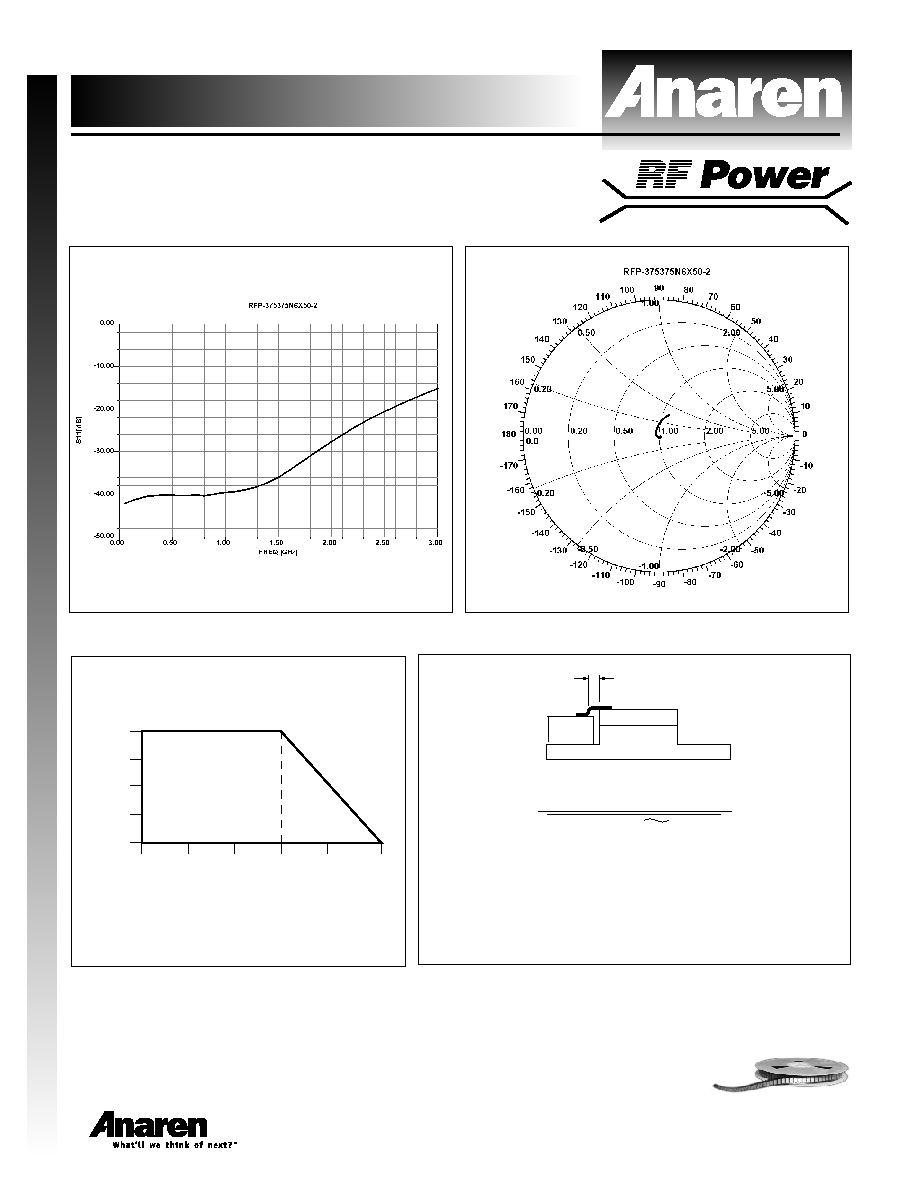
Typical Performance
2
Sales Desk USA: Voice: (800) 544-2414 Fax: (315) 432-9121
Sales Desk Europe: Voice: (+44) 23 92 232392 Fax: (+44) 23 92 251369
Power Derating
Suggested Mounting Procedures
SUGGESTED STRESS RELIEF METHODS
SCALE:
BOARD LOWER
THAN LEAD.
.025
(2 PLACES)
MIN.
1. Make sure that the devices are mounted on flat surfaces
(.001" under the device) to optimize the heat transfer.
2. Position device on mounting surface and solder in place
using an SN96 type solder.
3. Solder leads in place using an SN63 type solder with a
controlled temperature iron (700įF).
CASE TEMPERATURE --
įC
% OF RATED POWER
150
125
100
75
50
25
100
75
25
50
0
Available on Tape and Reel for Pick and Place Manufacturing.