
APEX MICROTECHNOLOGY CORPORATION ∑ TELEPHONE (520) 690-8600 ∑ FAX (520) 888-3329 ∑ ORDERS (520) 690-8601 ∑ EMAIL prodlit@apexmicrotech.com
INTRODUCTION
This easy-to-use kit provides a platform for the evaluation of
PWM amplifiers using the SA06 pin-out configuration. It can be used
to analyze a multitude of standard or proprietary circuit configura-
tions, and is flexible enough to do most standard amplifier test
configurations. The board is designed for surface mounting all
components except the switching amplifier.
The schematic is shown in Figure 2. Note that all of the compo-
nents shown on the schematic will probably not be used for any
single circuit. Some components will simply be omitted, while others
require installation of a jumper to complete the signal path.
Only components unique to the EK05 are provided in this kit.
Hardware similar to that shown in figure 1 must be obtained locally.
PARTS LIST
Part #
Description
Quantity
HS18
Heatsink
1
MS02
PC mount Cage Jacks
2 Bag/8 each
EVAL10
PC Board
1
60SPG00001
Spacer Grommets
4
TW05
Thermal Washer
1 Box/10
each
ZX7R105KTL
1
µ
F Cap ST2225B105K501LLXW, 1
ASSEMBLY
1. From the non-silk screen side, insert and solder cage jacks. Be
sure each one is fully seated.
2. From the non-silk screen side, push spacer grommets into PC
board until fully seated. Grommets will snug when screws are
inserted for heatsink mounting.
3. Apply TW05 thermal washer to the bottom of the SA06.
4. Use #14 sleeving to insulate and align at least 2 opposite pins of
the amplifier.
5. Mount amplifier to heatsink using #6 screws and nuts. Torque the
part to the specified 8 to 10 in-lbs (.9 to 1.13 N*M). Do not over
torque.
6. Install components as needed. External connections may be
soldered directly or standard banana jacks may be soldered to
these pads.
7. Insert amplifier pins into cage jacks and fasten board to heatsink.
Novacap
OX7R105KWN 1
µ
F Cap 1825B105K201N,
1
Novacap
BEFORE YOU GET STARTED
*
All Apex amplifiers should be handled using proper ESD precautions.
*
Always use the heatsink included in this kit with TW05 washer.
*
Always use adequate power supply bypassing.
*
Do not change connections while the circuit is powered.
*
Initially set all power supplies to the minimum operating levels allowed in the device data sheet.
*
Check for oscillations.
H T T P : / / W W W . A P E X M I C R O T E C H . C O M ( 8 0 0 ) 5 4 6 - A P E X ( 8 0 0 ) 5 4 6 - 2 7 3 9
M I C R O T E C H N O L O G Y
EVALUATION KIT FOR SA06 PIN-OUT
EK05
Heatsink
Switching Amplifier
Hex Nut 6-32 THD 1/4"
#8 or #10 Screw (1/2" - 3/4" LG)
Spacer Grommet
6-32 x 1/2 Lg. Screw
TW05 thermal washer
PC Board (Silkscreen side)
FIGURE 1.
Cage Jack
Solder as required
APEX MICROTECHNOLOGY CORPORATION ∑ 5980 NORTH SHANNON ROAD ∑ TUCSON, ARIZONA 85741 ∑ USA ∑ APPLICATIONS HOTLINE: 1 (800) 546-2739
EK05
EVALUATION KIT
FOR SA06 PIN-OUT
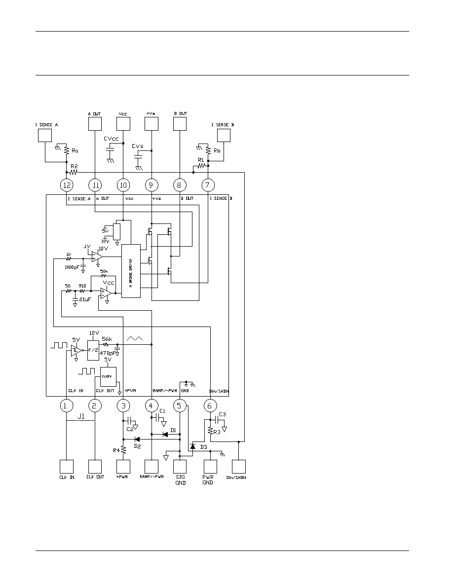
FIGURE 2. PCB SCHEMATIC.
A block diagram of the SA06 is shown in
Figure 2 along with pcb connections of all the
commonly used external components. Your
application circuit will not use all of the compo-
nents. Add those components required by your
circuit. You may have to jumper some compo-
nents to make the desired electrical connec-
tions. J1 is an optional way to connect the clock
circuit. Power supply bypassing is particularly
important and that is why high quality ceramic
chip capacitors are supplied with the kit. In
addition you may need to add a 10-50 uF or
larger capacitor on the +Vs pin. This additional
capacitor needs to be rated for switching opera-
tion. Note that the signal ground and power
ground are separated and tie together only at
the ground pin (5). A breadboarding area is
supplied which can accomodate 1 or 2 IC
amplifiers and associated components. The
large terminal pads can be used to solder wire
connections or bannana jacks.
SA06
*
*
*
*
Input protection, 10V zener diode.
APEX MICROTECHNOLOGY CORPORATION ∑ TELEPHONE (520) 690-8600 ∑ FAX (520) 888-3329 ∑ ORDERS (520) 690-8601 ∑ EMAIL prodlit@apexmicrotech.com
EVALUATION KIT
FOR SA06 PIN-OUT
EK05
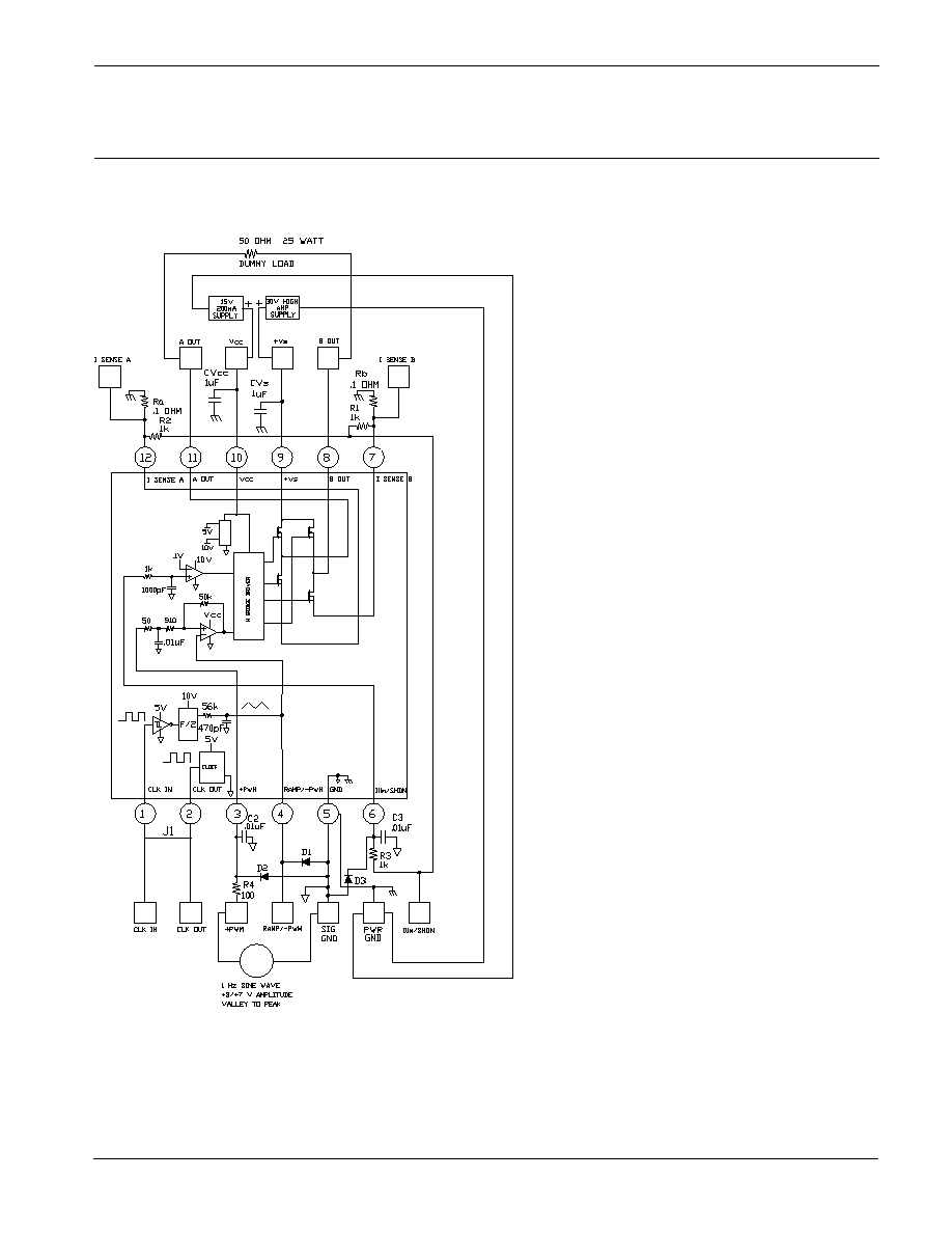
FIGURE 3. FUNCTIONAL TEST CIRCUIT
The schematic of Figure 3 can be used to
verify the functionality of your amplifier and help
you gain a familiarity with proper operation. At
either A Out or B Out, with respect to ground,
you should observe a square wave approxi-
mately 30 V in amplitude with a fixed frequency
and duty cycle that varies from approximately 0
to 100% at a rate of 1 Hz. The current limit is set
to 2 amps.
SA06
