APEX MICROTECHNOLOGY CORPORATION ∑ TELEPHONE (520) 690-8600 ∑ FAX (520) 888-3329 ∑ ORDERS (520) 690-8601 ∑ EMAIL prodlit@apexmicrotech.com
1
INTRODUCTION
This easy-to-use kit provides a platform for the evaluation of
linear power amplifiers circuits using the PA94/PA95 pin-out.
With ample breadboarding areas it is flexible enough to analyze
a multitude of standard or proprietary circuit configurations. Criti-
cal connections for power supply bypassing, compensation and
current limiting are pre-wired. Components not usually readily
available in engineering labs are provided. External connection
to the evaluation kit can be made via the terminals at the edge
of the circuit board. These terminal pads are suitable for stan-
dard banana jacks or direct soldering of wires. The schematic
is shown in Figure 1.
PARTS LIST
Part #
Description, Vendor
Quantity
HS27
Heatsink, Apex
1
EVAL23
PC Board, Apex
1
TW13
Thermal Washer, Apex
1 box, 10 ea.
P6KE440A
TransZorb, General
2
Semiconductor (440V)
CDC01
Capacitor .01µF 1kV,
2
Sprague 5GAS10
ASSEMBLY
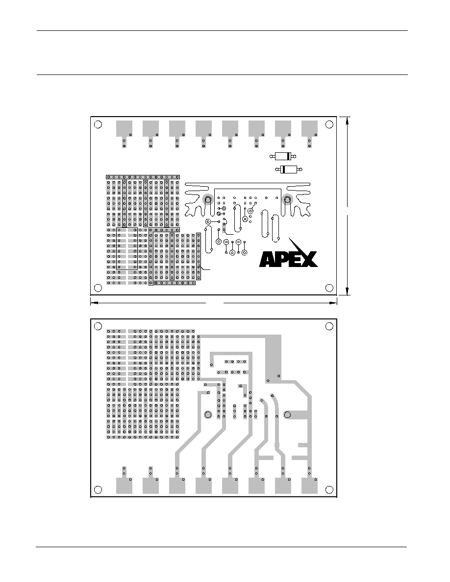
1. See Figures 2 & 3. Insert and solder the TransZorb diodes
at D3 and D4 (440V).
2. Insert and solder the disc bypass capacitors at C1 and
C2.
3. Insert the HS27 heatsink and solder the solderable studs
from the opposite side of the PCB.
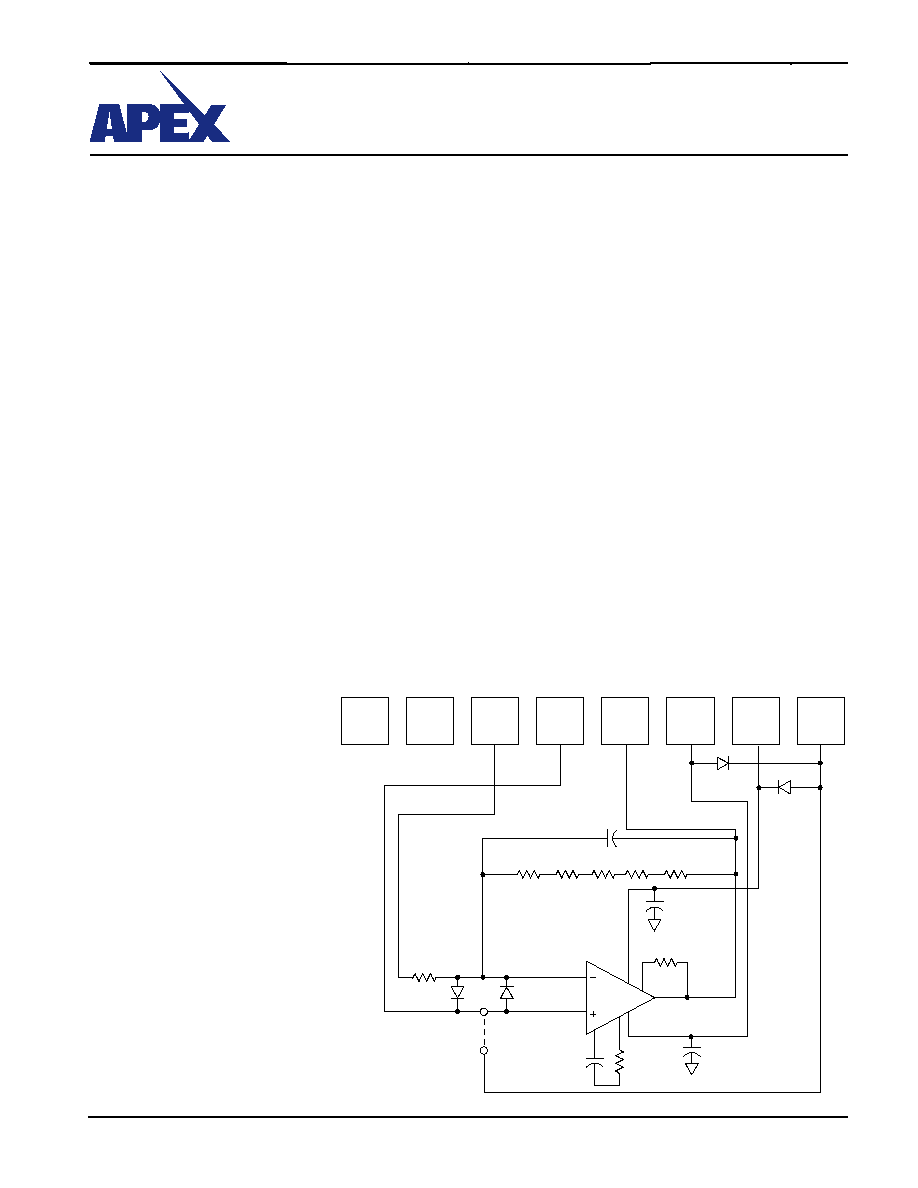
FIGURE 1.
Figure 1 shows the schematic of the
evaluation kit's pre-wired connections.
Components supplied with the kit are
marked with an asterisk (*). See the
amplifiers data sheet for full application
information.
4. Add banana jacks as necessary to complete connections
to external circuits and power supplies.
5. Insert the amplifier into the PCB mounting holes located
in the space between the heatsink fins. So not solder the
pins at this time.
6. Hang the TW13 thermal washer near the end of a 6-32 X
3/8" screw. Slightly pull the amplifier away from the heat
sink face. Use the screw to position the thermal washer
behind the amplifier and insert the screw into the mounting
hole of the heatsink. Use a 6-32 nut to secure the screw
from the opposite side of the heatsink. It is important that
the entire back surface of the amplifiers mounting tab be
in contact with the heatsink. Adjust the amplifiers position
and tighten the mounting screw as necessary for this to
be so.
7. Solder the amplifiers pins to the PCB.
8. Add other passive components as necessary to complete
your circuit.
9. Most common configurations will ground the non-invert-
ing pin of the amplifier. J1 is a convenient way to do this
if necessary for your application circuit.
10. The four holes at the corners of the circuit board are for
mounting #6 standoff spacers if desired.
11. R1-R5 are multiple feedback resistors in series. Commonly
available resistors do not have a breakdown voltage suf-
ficient to stand off the output voltage of the amplifier. Using
multiple resistors will divide down the voltage that each
resistor must withstand.
APEX MICROTECHNOLOGY CORPORATION ∑ 5980 NORTH SHANNON ROAD ∑ TUCSON, ARIZONA 85741 ∑ USA ∑ APPLICATIONS HOTLINE: 1 (800) 546-2739
2
FIGURE 2. PCB
EK19
EVALUATION KIT
FOR PA94/PA95 PIN-OUT
This data sheet has been carefully checked and is believed to be reliable, however, no responsibility is assumed for possible inaccuracies or omissions. All specifications are subject to change without notice.
EK19U REV B OCTOBER 2004 © 2004 Apex Microtechnology Corp.