 | –≠–ª–µ–∫—Ç—Ä–æ–Ω–Ω—ã–π –∫–æ–º–ø–æ–Ω–µ–Ω—Ç: AP8842 | –°–∫–∞—á–∞—Ç—å:  PDF PDF  ZIP ZIP |

Integrated Circuits Inc.
aP8842
Ver 1.3
1
A
PLUS MAKE YOUR PRODUCTION A-PLUS
V
OICE OTP IC
a
P8842 ≠ 42
VOICE OTP
A
PLUS INTEGRATED CIRCUITS INC.
Sales E-mail:
sales@aplusinc.com.tw
Address:
3 F-10, No. 32, Sec. 1, Chenggung Rd., Taipei,
Taiwan 115, R.O.C.
(115)
32
3
10.
TEL: 886-2-2782-9266
FAX: 886-2-2782-9255
WEBSITE :
http: //www.aplusinc.com.tw
Technology E-mail:
service@aplusinc.com.tw

Integrated Circuits Inc.
aP8842
Ver 1.3
2
42 sec VOICE OTP
Features
42 Sec Voice Length at 6 KHz
Combination of voice building blocks
extends the duration of playback
Voice data re-use saves memory space
Maximum 30 voice groups
8 trigger pins, S1 to S8 for the 8 voice
groups ( group1 ~ 8 )
SBT for sequential playblack the rest of
voice groups & for CPU mode trigger
S1 to S5 in CPU trigger mode to trigger
all 30 voice groups
Holdable, Unholdable, Edge, Level
triggering option
Debounce time : 22ms for both Key and
CPU mode @ 6K sampling rate
IRP interrupt pin for master reset
3 programmable Outputs for STP stop
pulse, BUSY and LEDs
Built-in oscillator with a single external
resistor to determine the sampling rate
Built-in D/A converter, EPROM
ADPCM data compression provides
high sound quality
Optional POP noise elimination function
C
OUT
pin drives speaker with a transistor
V
OUT1
and V
OUT2
drives buzzer or
speaker directly
Auto-power down
2.7V ≠ 3.8V single power supply
operation
Low standby current (<5uA at 3V)
Development Tools Support
General Description
aP8842 is a high quality voice synthesizer capable of varying playback duration. A proprietary
ADPCM algorithm is used. The audio message is stored in a 1M bits on-chip EPROM which can
store up to 42 seconds of voice data at 6 KHz sample rate.
The
aP8842 eliminates the need of complicated circuitry in voice playback but still achieves high
voice quality for different kind of sounds. Combinations in sections achieve longer playback duration.
A pair of PWM output pins, V
OUT1
and V
OUT2
provides direct drive to buzzer or speaker.
A current output pin, C
OUT
, enables the device to drive a speaker through a low cost NPN transistor.
No complex filtering or amplifier circuit is needed. An automatic ramp-down function eliminates
undesired noise at the end of playback.
Integrated Circuits Inc.
aP8842
Ver 1.3
3
Group of sections
The voice memory of the
aP8842 is subdivided into 254 memory blocks. Any combination of
playback of these memory blocks will form an individual voice group. A maximum of 30 groups are
available with triggering S1 to S5 pins together with the SBT pin in CPU trigger mode. In Key
trigger mode, S1 to S8 pins are used to trigger the beginning 8 voice groups. The rest of the voice
groups can be triggered one by one sequentially with the SBT pin.
Group Configuration
Data within each group are combinations of different fixed memory blocks of up to 254 blocks. They
are the fundamental building blocks for arranging playback without limiting sequencing. This
provides flexibility and allows data to be re-used, beneficial for applications with many repeated
sounds or words.
An example of group configuration is illustrated below:
Group no.
Section entry
Group 1
Block 1 + Block 2 + Block 3 ....... + Block 109
Group 2
Block 3 + Block 2
Group 3
Block 10 + Block 11 + Block 12
Group 4
Block 10 + Block 10 + Block 5
The entries of blocks for each group is truly random and without limitation. However, there is a limit
in the total number of entries for 30 voice groups, which is 896 entries in
aP8842. It is acceptable to
allocate all entries into only one group or distribute out to other groups. It depends on how many
groups of messages are required.
Programmable Options
Each groups in
aP8842 can have independent options. They are:
Edge or Level trigger
Unholdable or Holdable trigger
Re-triggerable or non-retriggerable
Outputs are programmable to LED1, LED2, BUSY and STOP pulse
Options that affect all voice groups are called whole chip options. They are:
Key trigger mode or CPU trigger mode
Ramp enable (for Cout drive) or Ramp disable (for Vout drive)
Integrated Circuits Inc.
aP8842
Ver 1.3
4
Output Selections
There are three independent output pins OUT1, OUT2 and OUT3, available for four combinations of
LED1, LED2, STOP and BUSY signals for each voice group.
Options
OUT1 OUT2 OUT3
1. LED2
LED1
BUSY
2. STOP
LED1
LED2
3. LED1
BUSY
STOP
4. LED1
BUSY
/BUSY
LED1 and LED2 are complemented outputs flashing at a fix interval. STOP pulse gives a long
enough positive pulse at the end of the playback for each group with option to enable or disable it.
BUSY is active high during voice playback.
Software Support
All those Options and Output selections can be set with a dedicated OTP compiler and programmer
software supplied by APLUS.
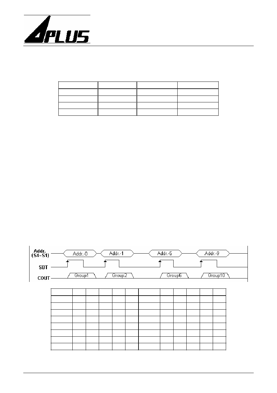
Key trigger mode and CPU trigger mode
In Key trigger mode, S1 to S8 will trigger eight voice groups. The rest of the voice groups can only
be triggered by SBT sequential trigger pin.
In CPU trigger mode, binary data is input through S5 to S1. A high pulse is input to SBT pin with
pulse width equal to or longer than the debounce time to strobe the data to initial the playblack. Data
patterns "11110" and "11111" are reserved and not allowed.
Group-n
S5
S4 S3 S2
S1
Group-n
S5
S4
S3 S2 S1
Group1
0 0 0 0 0
Group9
0 1 0 0 0
Group2
0 0 0 0 1
Group10
0 1
0 0 1
Group3
0 0 0 1 0
Group11
0 1
0 1 0
Group4
0 0 0 1 1
Group12
0 1
0 1 1
Group5
0 0 1 0 0
Group13
0 1
1 0 0
Group6
0 0 1 0 1
Group14
0 1
1 0 1
Group7
0 0 1 1 0
Group15
0 1
1 1 0
Group8
0 0 1 1 1
Group16
0 1
1 1 1

Integrated Circuits Inc.
aP8842
Ver 1.3
5
Group-n
S5
S4 S3 S2
S1
Group-n
S5
S4
S3 S2 S1
Group17
1 0 0 0 0
Group25
1 1 0 0 0
Group18
1 0 0 0 1
Group26
1 1
0 0 1
Group19
1 0 0 1 0
Group27
1 1
0 1 0
Group20
1 0 0 1 1
Group28
1 1
0 1 1
Group21
1 0 1 0 0
Group29
1 1
1 0 0
Group22
1 0 1 0 1
Group30
1 1
1 0 1
Group23
1 0 1 1 0
Reserve
1 1
1 1 0
Group24
1 0 1 1 1
Reserve
1 1
1 1 1
Block Diagram
Absolute Maximum Rating
Symbol Rating
Unit
V
DD
- V
SS
-0.5 ~ +4.5
V
V
IN
V
SS
- 0.3<V
IN
<V
DD
+ 0.3
V
V
OUT
V
SS
<V
OUT
<V
DD
V
T (Operating)
-10 ~ +60
T (Storage)
-55 ~ +125