LOW TO MEDIUM POWER AC/DC POWER SUPPLIES 25W AC/DC Universal Input Switch Mode Power Supplies
1
2 YEAR WARRANTY
NFS25 Series
D u a l a n d t r i p l e o u t p u t
∑
5.0 x 3.0 x 1.2 inch package (1U applications)
∑
Industry standard package
∑
Overvoltage and short circuit protection
∑
25W with free air convection cooling
∑
EN55022, EN55011 conducted emissions level A
∑
UL, VDE and CSA safety approvals
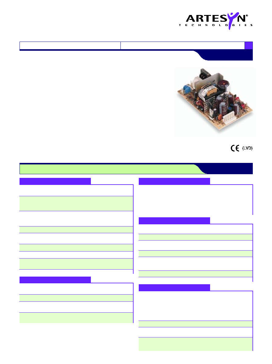
The NFS25 series is a 25W universal input AC/DC power supply on a 5 x 3 inch card
with a maximum component height of 1.2 inches for use in 1U applications. The NFS25
series is available with a wide range of models in the industry standard 5 x 3 inch
footprint and has proven itself to be reliable and versatile product for a wide range of
communication and industrial applications. The NFS25 provides 25W of output power
with free air convection cooling which can be boosted to 30W with 20CFM of air.
Standard features include OVP and short circuit protection. The series, with full
international safety approval and the CE mark, meets conducted emissions EN55022
level A. The NFS25 series is designed for use in low power data networking, computer,
telecom and industrial applications such as wireless switchers, hubs, POS terminals,
PABX's and machine control. This list is not exclusive as the generic feature of the
series with industry standard output configurations provide a solution for most high
volume applications including many industrial applications.
All specifications are typical at nominal input, full load at 25∞C unless otherwise stated
EMC CHARACTERISTICS
Conducted emissions
EN55022, FCC part 15
Level A
Radiated emissions
EN55022, FCC part 15
Level A
ESD air
EN61000-4-2, level 3
Perf. criteria 1
ESD contact
EN61000-4-2, level 4
Perf. criteria 1
Surge
EN61000-4-5, level 3
Perf. criteria 1
Fast transients
EN61000-4-4, level 3
Perf. criteria 1
Radiated immunity
EN61000-4-3, level 3
Perf. criteria 2
Conducted immunity
EN61000-4-6, level 3
Perf. criteria 1
GENERAL SPECIFICATIONS
Hold-up time
110VAC input
16ms
230VAC input
80ms
Efficiency
25W output
70% typical
Isolation voltage
Input/output
3000VAC
Input/chassis
1500VAC
Switching frequency
Variable
Approvals and
IEC950, IEC1010, EN60950
standards
UL1950, VDE0805
(See Note 10)
CSA C22.2 No. 950
Weight
280g (9.6oz)
MTBF (See Note 9)
MIL-HDBK-217E, 25∞C
170,000 hours
ENVIRONMENTAL SPECIFICATIONS
Thermal performance
0∞C to 50∞C ambient,
25W max.
(See Notes 6, 7, 8)
convection cooled
50∞C to +70∞C ambient
Derate to
convection cooled
50% load
Peak (0∞C to +50∞C,
35W
max. 60 seconds)
Non-operating
≠40∞C to +85∞C
Relative humidity
Non-condensing
5% to 95% RH
Altitude
Operating
10,000 feet max.
Non-operating
30,000 feet max.
Vibration
Random vibration
2.4G rms approx.
Three orthogonal axes
5Hz to 500Hz
10 min. test per axis
OUTPUT SPECIFICATIONS
Output power
Continuous
25W
(See Note 2)
Peak (60s)
35W
Line regulation
Main output (Output 1)
±0.2% max.
LL to HL, FL
Output 2
±1% max.
Output 3
±0.2% max.
Total regulation
Main output (Output 1)
±2.0% max.
(See Notes 4, 5)
Auxiliary output 2
see table
Auxiliary output 3
see table
Overshoot/undershoot
At turn-on
0%
Transient response
+5V
±120mV max. dev.
(1.5 to 3A step)
500µs recovery
Temperature coefficient
All outputs
±0.02%/∞C max.
Overvoltage protection
+5V output
6.25V ±0.75V
Output power limit
Primary power
60W Pin limit max.
limited
35W Pout limit min.
Short circuit protection
Continuous
INPUT SPECIFICATIONS
Input voltage range
Universal input
85 to 264VAC
120 to 370VDC
Input frequency range
47 to 440Hz
Input surge current
110VAC, cold start
15A max.
230VAC, cold start
32A max.
Safety ground
132VAC, 60Hz
0.62mA max.
leakage current
264VAC, 50Hz
1mA max.
SPECIFICATIONS
File Name: NFS25.PDF Rev: 01 Jan 2000
For the most current data and application support visit www.artesyn.com/powergroup/products.htm
Notes
1
Natural convection cooling.
2
Peak output current lasting less than 60 seconds with duty cycle less than
5%. During peak loading, outputs may go outside of total regulation limits.
Total peak power output is 35 Watts.
3
Figure is peak-to-peak. Output noise measurements are made across a
50MHz bandwidth using a 12 inch twisted pair, terminated with a 47µF
capacitor.
4
Total regulation is defined as the static output regulation at 25∞C, including
initial tolerance, line voltage within stated limits, load currents within stated
limits and output voltages adjusted to their factory settings. Also, 0.5
I
A
/
I
B
3 to maintain stated regulation. This does not apply to the NFS25-
7628.
5
The NFS25-7628 has separately regulated +12V and -12V outputs. The
loading condition in note 4 does not apply.
6
Derate linearly from 25 Watts at 50
o
C to 12.5 Watts at 70
o
C.
7
Derating curve is application specific for ambient temperatures > 50∞C, for
optimum reliability no part of the heatsink should exceed 120
o
C and no
semiconductor case temperature should exceed 125
o
C.
8
Caution: Allow a minimum of 1 second after disconnecting the power
before making thermal measurements.
9
A 4 Watt minimum load is required to achieve design MTBF.
10
This product is only for inclusion by professional installers within other
equipment and must not be operated as a stand alone product.
NFS25 Series
D u a l a n d t r i p l e o u t p u t
LOW TO MEDIUM POWER AC/DC POWER SUPPLIES 25W AC/DC Universal Input Switch Mode Power Supplies
2
www.artesyn.com
File Name: NFS25.PDF Rev: 01 Jan 2000
AC mating connector
Molex 09-50-3031 or equivalent with Molex 08-50-0105 crimp terminals or
equivalent
DC mating connector
Molex 09-91-0600 or equivalent with Molex 08-50-0164 crimp terminals or
equivalent
OUTPUT
OUTPUT CURRENTS
RIPPLE
(3)
TOTAL
MODEL NUMBER
(D)
VOLTAGE
MIN
(9)
MAX
(1)
PEAK
(2)
REGULATION
(4)
+5.1V (I
A
)
0A
2.0A
5.0A
50mV
±2.0%
NFS25-7608
(4)
+12.0V (I
B
)
0A
1.5A
3.0A
120mV
±5.0%
≠12.0V
0A
0.2A
1.0A
120mV
±5.0%
+5.1V
0A
3.0A
5.0A
50mV
±2.0%
NFS25-7628
(5)
+12.0V
0A
0.2A
1.0A
120mV
±2.0%
≠12.0V
0A
0.2A
1.0A
120mV
±2.0%
+5.1V (I
A
)
0A
2.0A
5.0A
50mV
±2.0%
NFS25-7629
(4)
+12.0V (I
B
)
0A
1.5A
3.0A
120mV
±5.0%
PIN CONNECTIONS
J1
-7608
-7628
-7629
Pin 1
AC Line
AC Line
AC Line
Pin 2
AC Neutral
AC Neutral
AC Neutral
J2
Pin 1
+12V
+12V
+12V
Pin 2
+5.1V
+5.1V
+5.1V
Pin 3
+5.1V
+5.1V
+5.1V
Pin 4
Return
Return
Return
Pin 5
Return
Return
Return
Pin 6
≠12V
≠12V
N/C
P1
Pin 1
Safety Ground
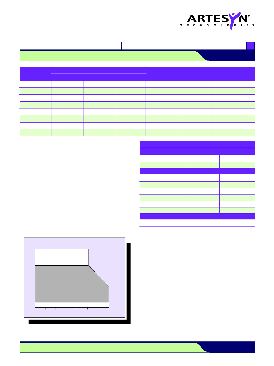
12.5W
25W
0
∞
C 10
∞
C 20
∞
C 30
∞
C 40
∞
C 50
∞
C 60
∞
C 70
∞
C
DERATING CURVE
(See Notes 6, 7, 8, 9)
Output Power (Watts)
NATURAL
CONVECTION
COOLING
0W
35W
4W MIN. LOAD REQUIRED TO ACHIEVE DESIGN MTBF
4W
PEAK POWER, 60 SECONDS
Data Sheet © Artesyn TechnologiesÆ 2002
The information and specifications contained in this data sheet are believed to be correct at time of publication. However, Artesyn Technologies accepts no responsibility for consequences arising
from printing errors or inaccuracies. Specifications are subject to change without notice. No rights under any patent accompany the sale of any such product(s) or information contained herein.
For the most current data and application support visit www.artesyn.com/powergroup/products.htm
NFS25 Series
D u a l a n d t r i p l e o u t p u t
LOW TO MEDIUM POWER AC/DC POWER SUPPLIES 25W AC/DC Universal Input Switch Mode Power Supplies
3
www.artesyn.com
File Name: NFS25.PDF Rev: 01 Jan 2000
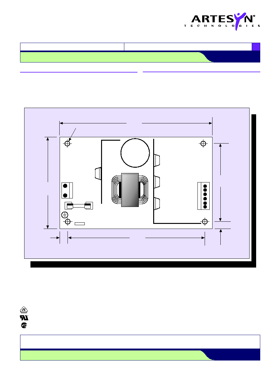
0.156 (3.96) Dia.
(4 Places)
5.00
(127.00)
NON-METALLIC
STAND-OFF
(SEE NOTE A)
MAXIMUM
COMPONENT
HEIGHT 1.2
inches
C5
J2
1
P1 (SEE NOTE C)
F1
J1
N
~
L
Q1
F 3.15A, H 250VAC
2.550
(64.8)
0.22
(5.59)
3.00
(76.2)
0.22 (5.59)
4.55
(115.8)
~
ALL DIMENSIONS IN INCHES (mm)
T1
International Safety Standard Approvals
VDE0805/EN60950/IEC950/IEC1010
File No. 10401-3336-1044 Licence No. 2559, 1651
UL1950 File No. E136005
CSA C22.2 No. 950 File No. LR41062C
Mechanical Notes
A
In order to meet safety requirements, a non-metallic stand-off is mandatory
for one hole as specified in the mechanical drawing above.
B
The ground pad of the mounting hole near P1 allows system grounding
through a metal stand-off.
C
To improve conducted noise, the ground pad of the mounting hole near the
output connector should be connected with the ground pad of the
mounting hole near P1. Use metal stand-offs attached to a common metal
chassis. This connection also significantly attenuates common mode noise.
D
A standard L-bracket and cover is available for mounting which contains all
screws, connectors and necessary mounting hardware. Order part number
`NFS40 COVER KIT'.