LOW TO MEDIUM POWER AC/DC POWER SUPPLIES 70W AC/DC Universal Input Switch Mode Power Supplies
1
2 YEAR WARRANTY
NLP70 Series
T r i p l e o u t p u t
∑
Provides up to 10.5A on either 3.3V or 5V
∑
5.5 x 3.0 inch card and 1.26 inch package (1U applications)
∑
3.3V, 5V and 12V triple
∑
EN61000-3-2 compliant
∑
Overvoltage and short circuit protection
∑
EN55022, EN55011 conducted emissions level B
∑
EN61000-4-2, -3, -4, -5, -6 immunity compliant
∑
Mounting holes as per NLP65 series, easy upgrade
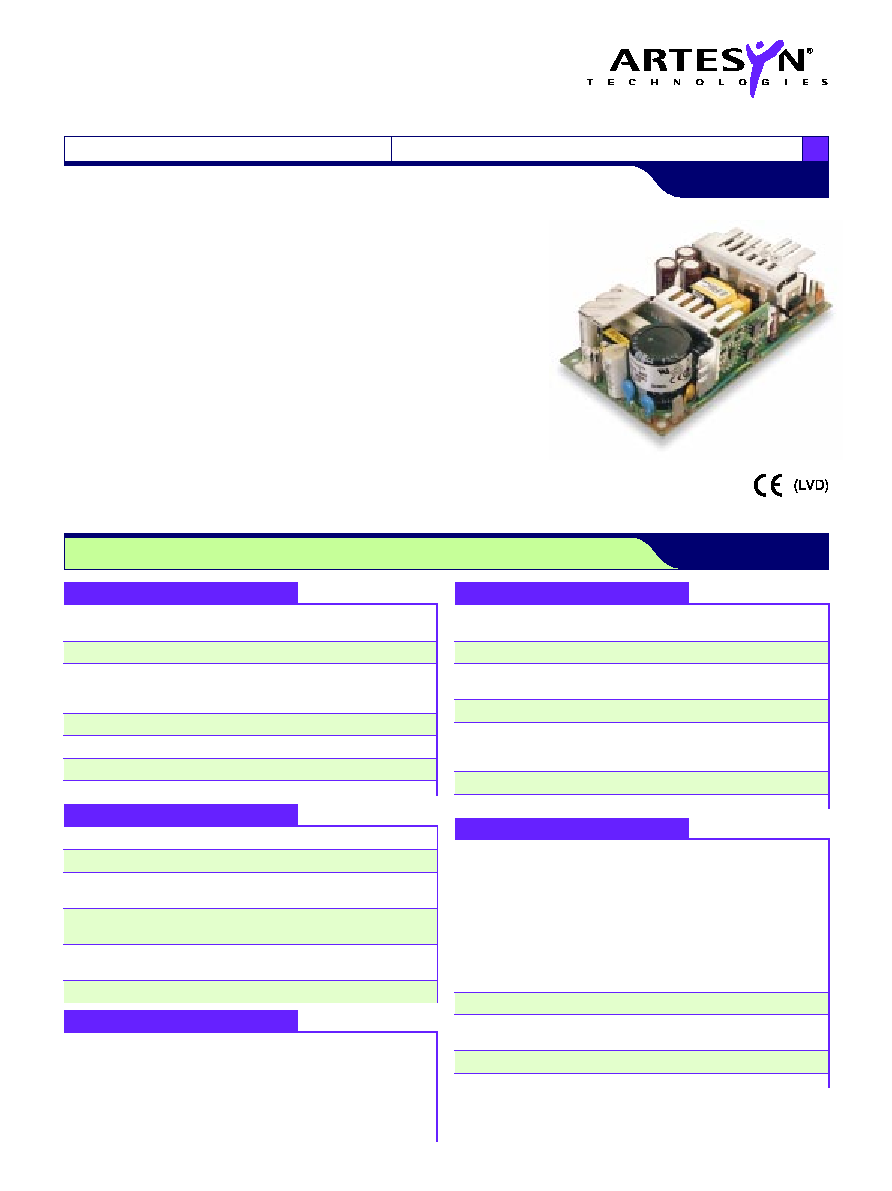
The NLP70-9693 is a 70W (with forced air) universal input AC/DC power supply on a
5.5 x 3 inch card with a maximum component height of 1.26 inches for use in 1U
applications. The model has input harmonic current correction making the series ideal
for product designs that need to comply with EN61000-3-2 legislation. The NLP70
provides 52.5W of output power with free air convection cooling which can be boosted
to 70W with 20CFM of air. The NLP70, with full international safety approval and the CE
mark, meets conducted emissions EN55022 level B and has immunity compliance to
EN61000-4-2, -3, -4, -5, -6. The NLP70 series is designed for use in low power data
networking, computer and telecom applications using 3.3V or 5V logic. The NLP70 can
provide the same current on either the 3.3V or 5V channel making it ideal for
applications using a mixture of 3.3V and 5V logic or for applications in transition from
5V to 3.3V logic.
All specifications are typical at nominal input, full load at 25∞C unless otherwise stated
GENERAL SPECIFICATIONS
Hold-up time
120VAC @ 60Hz
16ms @ 55W
230VAC @ 50Hz
78ms @ 55W
Efficiency
120VAC, 65W
70% typical
Isolation voltage
Input/output
3000VAC
Input/chassis
1500VAC
Switching frequency
Fixed
100kHz, ±5kHz
Approvals and
EN60950, VDE0805
standards
IEC950, UL1950
(See Notes 8, 9)
CSA C22.2 No. 950
Weight
300g (10.7 oz)
MTBF
MIL-HDBK-217F
150,000 hours min.
ENVIRONMENTAL SPECIFICATIONS
Thermal performance
Operating ambient,
0∞C to +70∞C
(See Notes 1, 2, 3, 11)
(See derating curve)
Non-operating
-40∞C to +85∞C
50∞C to 70∞C ambient,
Derate to
convection cooled
50% load
0∞C to 50∞C ambient,
52.5W
convection cooled
0∞C to 50∞C ambient,
70W
20CFM forced air (See Note 10)
Peak (0∞C to +50∞C, 60s)
See table
Relative humidity
Non-condensing
5% to 95% RH
Altitude
Operating
10,000 feet max.
Non-operating
30,000 feet max.
Vibration (See Note 5)
5Hz to 500Hz
2.4G rms peak
Shock
per MIL-STD-810E
516.4 Part IV
OUTPUT SPECIFICATIONS
Total regulation
3.3V and 5V
±2.0%
(line and load)
12V
±5.0%
Rise time
At turn-on
1.0s, max.
Transient response
Main output
5.0% or 250mV
25% step
max. dev., 1ms max.
at 0.1A/µs
recovery to 1.0%
Temperature coefficient
±0.02%/∞C
Overvoltage protection
Main outputs
125%, ±10%
Short circuit protection
Cyclic operation
Continuous
Minimum output current
(See Note 6)
INPUT SPECIFICATIONS
Input voltage range
Universal input
90 to 264VAC
Input frequency range
47Hz to 63Hz
Input surge current
120VAC
17A max.
(cold start)
230VAC
32A max.
Safety ground
120VAC, 60Hz
0.7mA
leakage current
230VAC, 50Hz
1.4mA
Input current
120VAC, with PFC
1.05A rms
230VAC, with PFC
0.55A rms
Input fuse
UL/IEC127
250VAC S 3.15A
EMC CHARACTERISTICS
(10)
Conducted emissions
EN55022, FCC part 15
Level B
Radiated emissions
EN55022, FCC part 15
Level A
ESD air
EN61000-4-2, level 3
ESD contact
EN61000-4-2, level 4
Surge
EN61000-4-5, level 3
Fast transients
EN61000-4-4, level 3
Radiated immunity
EN61000-4-3, level 3
Conducted immunity
EN61000-4-6, level 3
SPECIFICATIONS
File Name: NLP70.PDF Rev: 26 Mar 2001

For the most current data and application support visit www.artesyn.com/powergroup/products.htm
Notes
1
Free air convection cooling.
I
5
= 10.5A max.; I
3.3
= 10.5A max.; I
3.3
+ I
5
< 10.6A; Po = 52.5W max.
2
20CFM forced air.
I
3.3
= 13A max.; I
5.5
= 13A max.; I
3.3
+ I
5
< 15A; Po = 70W max.
3
Peak output current lasting less than 60 seconds with duty cycle less
than 5%. During peak loading, output voltage may exceed total
regulation limits.
4
Figure is peak-to-peak for convection power rating. Output noise
measurements are made across a 20MHz bandwidth using a 6 inch
twisted pair, terminated with a 10µF electrolytic capacitor and a 0.1µF
ceramic capacitor.
5
Three orthogonal axes, random vibration 10 minutes for each axes, 2.4G
rms 5Hz to 500Hz.
6
To maintain stated regulation then:
I
12
/ I
(A)
2 and I
(A)
0.1A.
7
For optimum reliability, no part of the heatsink should exceed 120∞C, and
no semiconductor case temperature should exceed 130∞C.
8
CAUTION: Allow a minimum of 1 second after disconnecting line power
when making thermal measurements.
N
9
This product is only for inclusion by professional installers within other
equipment and must not be operated as a stand alone product.
10
Conducted and radiated emissions testing were performed using the
standard EN55022 set-up with a stand alone NLP70-9693 unit placed on
a grounded metal plate with a line choke on the AC input and ground
wires (i.e. the wires are looped through an EMI suppression toroid).
For system compliance it is usually necessary to install an `off-the-shelf'
AC inlet with an integral line filter in the system chassis or to install a line
choke on the input wires as close as possible to AC entry point of the
system chassis. Please contact the applications group at Artesyn for
assistance with EMI compliance.
11
All models require a minimum mounting stand-off of 0.25 inches
(6.35mm) in the end use product.
12
12V is a floating output and can be referenced negative or positive.
NLP70 Series
T r i p l e o u t p u t
LOW TO MEDIUM POWER AC/DC POWER SUPPLIES 70W AC/DC Universal Input Switch Mode Power Supplies
2
www.artesyn.com
File Name: NLP70.PDF Rev: 26 Mar 2001
OUTPUT
OUTPUT CURRENT
RIPPLE
(4)
TOTAL
MODEL
VOLTAGE
TYP.
(1)
AIR
(2)
PEAK
(3)
REGULATION
(6)
NUMBER
+5V (I
A
)
10.5A
13A
14A
50mV
±2.0%
NLP70-9693
+3.3V (I
B
)
10.5A
13A
14A
50mV
±2.0%
+12V
(12)
0.65A
0.8A
0.8A
120mV
±5.0%
Output Power (Watts)
26W
52.5W
70W
20CFM FORCED AIR COOLING
35W
NATURAL
CONVECTION
COOLING
DERATING CURVE
0∞C
10∞C 20∞C 30∞C 40∞C 50∞C 60∞C
70∞C
INPUT
PIN CONNECTIONS
J1
Pin 1
AC Line
Pin 2
No Pin
Pin 3
AC Neutral
J2
Pin 1
Safety Ground
OUTPUT PIN CONNECTIONS
J5
FUNCTION
Pin 1
3.3V
Pin 2
3.3V
Pin 3
Return
Pin 4
Return
Pin 5
Return
Pin 6
5V
Pin 7
5V
J3
FUNCTION
Pin 1
12V Return
Pin 2
12V
(12)
C19
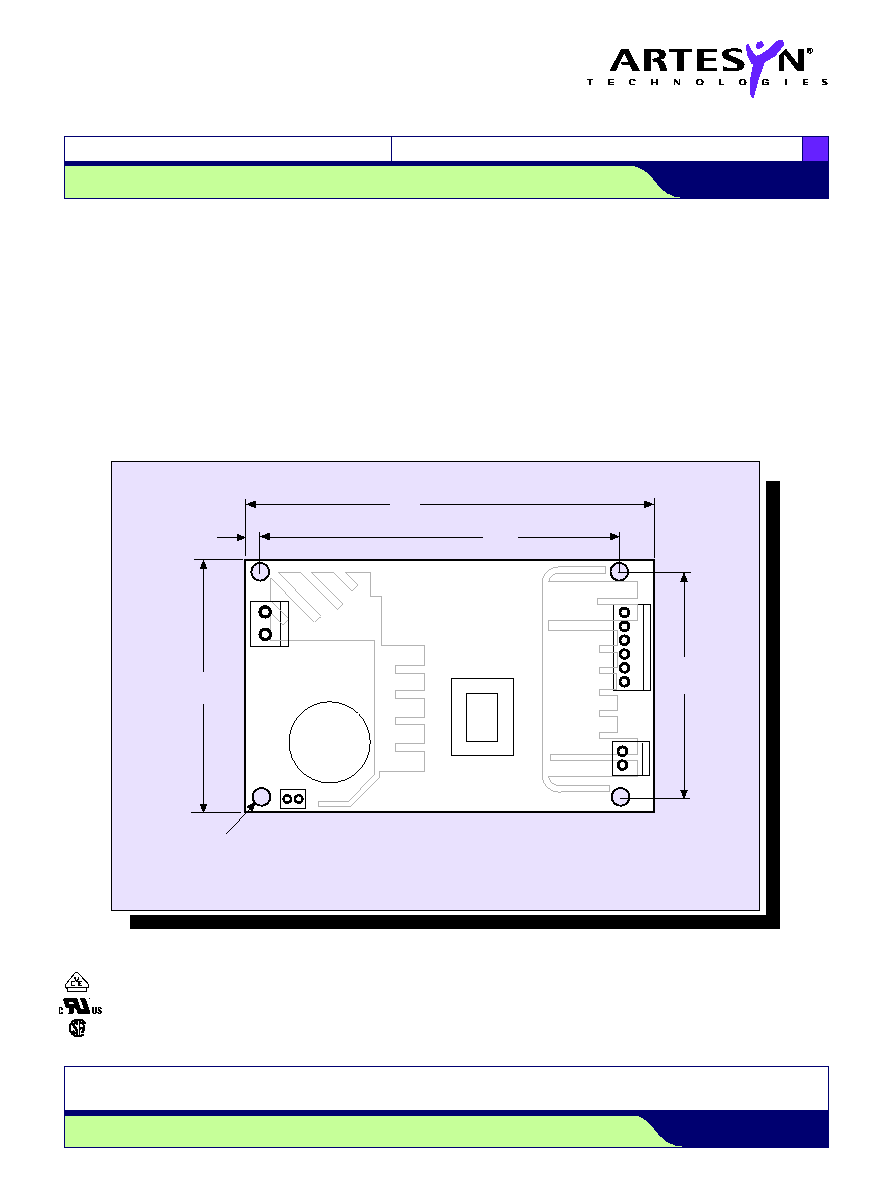
ALL DIMENSIONS IN INCHES (mm)
5.50
(139.70)
MAXIMUM COMPONENT
HEIGHT 1.26 (32.00)
7
J5
J2
1
4.550
(115.57)
2.550
(64.770)
TOLERANCE: .xxx
±
0.005"
.xx
±
0.02"
0.225
(5.715)
3.00
(76.20)
Mounting
Hole Diameter
0.156 (4.00)
N
L
J1
3
1
J3
2
1
T1
Input and output connectors
Mating connectors
AC (J1) connector type
AC (J1) mating connector type
Molex 26-60-4030 type.
Molex 09-50-3031 or equivalent with Molex
08-50-0105 or equivalent crimp terminals.
DC (J3) connector type
DC (J3) mating connector type
Molex 26-60-4020 type.
Molex 09-50-3021 with Molex 2478 phosphor
bronze crimp terminals or equivalent.
DC (J5) connector type
DC (J5) mating connector type
Molex 26-60-4070 type.
Molex 09-50-3071 with Molex phosphor
bronze crimp terminals or equivalent.
Note: The input and output connectors are the same as those
used on NFS40, NAL40, NAN40, NLP40 and NLP65.
Earth (J2) connector type
Earth (J2) mating connector type
Male 0.250 quick disconnect type.
Molex 90028.
International Safety Standard Approvals
VDE0805/EN60950/IEC950
UL1950 approval pending
CSA C22.2 No. 950 approval pending
Data Sheet © Artesyn TechnologiesÆ 2002
The information and specifications contained in this data sheet are believed to be correct at time of publication. However, Artesyn Technologies accepts no responsibility for consequences arising
from printing errors or inaccuracies. Specifications are subject to change without notice. No rights under any patent accompany the sale of any such product(s) or information contained herein.
For the most current data and application support visit www.artesyn.com/powergroup/products.htm
NLP70 Series
T r i p l e o u t p u t
LOW TO MEDIUM POWER AC/DC POWER SUPPLIES 70W AC/DC Universal Input Switch Mode Power Supplies
3
www.artesyn.com
File Name: NLP70.PDF Rev: 26 Mar 2001