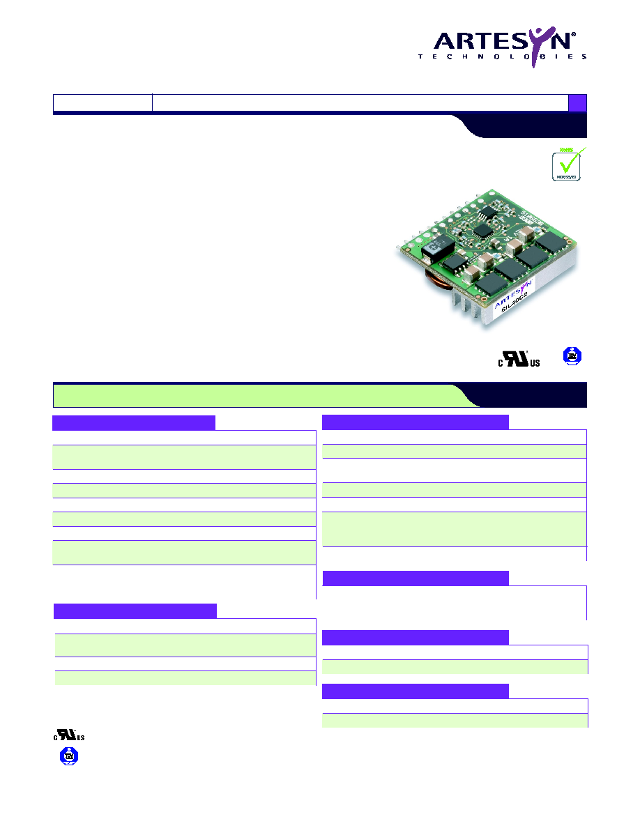
SIL40C2 Series
4.5-13.8 Vin Single Output
File Name: sil40c2.pdf Rev: 15 Mar 2006
March 15, 2006
2 year warranty
∑
40 a current rating
∑
Input voltage range: 4.5-13.8 V
∑
Output voltage: 0.6-5 V
∑
Industry leading value
∑
Cost optimized design
∑
excellent transient response
∑
Output enable
∑
Output voltage adjustability
∑
Pathway for future upgrades
∑
Supports silicon voltage migration
∑
resulting in reduced design-in and qual time
∑
roHS compliant
The SIL40C2 series is a new high density open frame non-isolated converter
for space sensitive applications. This model has a wide input range (4.5-13.8
Vdc) and offers a wide 0.6-5 V output voltage range with 40 A load capability.
An external resistor adjusts the output voltage from its pre-set value of 0.6 V to
any value up to the 5 V maximum. Typical efficiencies for the models are 91%
for the 12 V input version. The SIL40C2 series offers remote ON/OFF and
over-current protection as standard.
DC-DCCONVERTERS
C Class Non-isolated
1
NEWProduct
All specifications are typical at nominal input, full load at 25 ∞C unless otherwise stated
SPECIFICATIONS
Output voltage
(See Note 5)
0.6-5 V
Output setpoint
accuracy
0.1% trim resistors
±1.0%
Line regulation
Low line to high line
±0.2%
Load regulation
Full load to min. load
±0.5%
Min/max load
0 A/40 A
Overshoot
At turn-on
0.5% max.
Undershoot
At turn-off
100 mV max.
Ripple and noise
5 Hz to 20 MHz
(See Note 1)
25 mV
Vin = 5 V, Vout = 2.5 V
Transient response
(See Notes 1, 2)
150 mV max. deviation
30 µs recovery within
regulation band
OUTPUT SPECIFICATIONS
Efficiency
Vin=5 V, Vo=2.5 V, lo=20 A
94% Typ.
Switching frequency
Fixed
500 kHz
Approvals and
standards (pending)
EN60950
UL/cUL60950
Material flammability
UL94V-0
Weight
17 g/0.06 oz.
MTBF
12 V @ 40 ∞C
100% load
Bellcore 332
6,749,409 hours
Coplanarity
150 µm
GENERAL SPECIFICATIONS
Thermal performance
(See Note 5)
Operating ambient,
temperature
Non-operating
0 ∞C to +70 ∞C
-40 ∞C to +125 ∞C
ENVIRONMENTAL SPECIFICATIONS
INPUT SPECIFICATIONS
Input voltage range
4.5-13.8 Vdc
Input current
Minimum load
Remote OFF
50 mA
5 mA
Input current (max.)
(See Note 3)
25 A @ Io max.
Start-up time
Remote ON/OFF
3 ms
Short-circuit
Hiccup, non-latching
Over voltage
Hiccup, non-latching
PROTECTION
Input capacitance
(See Note 6)
0 µF
Output capacitance
(See Note 7)
0 µF
RECOMMENDED SYSTEM CAPACITANCE
UL/cUL CAN/CSA 22.2 No. E139421
UL60950 File No. TBD
TÐV Product Service (EN60950) Certificate No. TBD
CB report and certificate to IEC60950
International Safety Standard Approvals

SIL40C2 Series
4.5-13.8 Vin Single Output
File Name: sil40c2.pdf Rev: 15 Mar 2006
March 15, 2006
OUTPUT
INPUT
OVP
OUTPUT
OUTPUT
OUTPUT
EFFICIENCY
REGULATION
MODEL
POWER
VOLTAGE
VOLTAGE
CURRENT CURRENT
(TYP.)
LINE LOAD
NUMBER
(8, 9)
(MAX.)
(MIN.)
(MAX.)
200 W 4.5-13.8 Vdc N/A 0.6-5 Vdc
0 A
40 A 94% ±0.2% ±0.5% SIL40C2-00SADJ-VJ
For the most current data and application support visit www.artesyn.com/powergroup/products.htm
NEWProduct
DC-DC CONVERTERS
C Class Non-isolated
2
Part Number System with Options
Product Family
SIL = Single In Line
SMT = Surface Mount
Rated Output Current
06 = 6 A
15 = 15 A
20 = 20 A
30 = 30 A
40 = 40 A
Input Voltage
00 = 4.5-13.8 V
Performance
C = Cost Optimized
The ultra-wide output voltage trim range offers major advantages to users
who select the SIL40C2. It is no longer necessary to purchase a variety of
modules in order to cover different output voltages. The output voltage can
be trimmed in a range of 0.6-5 V. When the SIL40C2 converter leaves the
factory the ouput has been adjusted to the default voltage of 0.6 V.
Output Voltage Adjustment of the SIL40C2 Series
Mounting Option
V = Vertical
H = Horizontal
Output Voltage
Single Adjustable Output
Generation
Blank = Standard Part
2 = Increased Current Density
S I L 4 0 C 2 - 0 0 S A D J - V J
RoHS Compliance
(8)
J = Pb-free (RoHS 6/6 compliant)
Notes
1
Measured as per recommended system capacitance.
2
di/dt = 10 A/µs, Vin = Nom, Tc = 25 ∞C, load change = 0.75 lo to
full lo and full lo to 0.75.
3
External input fusing is recommended.
4
Additional part numbers may be available with different output
voltages.
5
Airflow dependent, 100 LFM minimum required.
6
No capacitor needed for ripple current capability.
7
No capacitor needed for stability.
8
TSE RoHS 5/6 (non PB-free) compliant versions are also available
on special request, please contact your local sales representative
for details.
9
NOTICE: Some models may not support all options. Please
contact your local Artesyn representative or use the on-line model
number search tool at http://www.artesyn.com/powergroup/
products.htm to find a suitable alternative.
7,8
10,11
6
9
5
1,2,3
4
SIL40C2
Enable
V
in
GND
R
trim
(for trim
down)
C
out
R
L
O
A
D
Power Good
V
out
+R
sense
C
in
Figure 1: Standard Application Drawing

SIL40C2 Series
4.5-13.8 Vin Single Output
File Name: sil40c2.pdf Rev: 15 Mar 2006
March 15, 2006
Figure 2: Vertical Mount Mechanical Drawing
Figure 3: Horizontal Mount Mechanical Drawing
PIN CONNECTIONS
PIN NO.
FUNCTION
1
Vout
2
Vout
3
Vout
4
Trim
5
Enable
6
Power Good
7
Ground
8
Ground
9
(+) Sense
10
Vin
11
Vin
12
*Mech Support
13
*Mech Support
For the most current data and application support visit www.artesyn.com/powergroup/products.htm
NEWProduct
DC-DC CONVERTERS
C Class Non-isolated
3
* Horizontal and SMT version only
Dimensions in Inches (mm)
Tolerances (unless otherwise specified)
2 Places ±0.030 (±0.76)
3 Places ±0.010 (±0.25)
0.100 (2.54)
1.050 (26.67)
9 PLACES
1.100 (27.94)
1.200 (30.48)
0.050 (1.27) REF
0.140 (3.56) TYP
PIN 1
0.050 (1.27) TYP
0.255 (6.48)
0.110 (2.79)
0.427 (10.85)
0.025 (0.64) ±.001
SQ PINS TYP
0.062 (1.57) REF
0.100 (2.54) TYP
Dimensions in Inches (mm)
Tolerances (unless otherwise specified)
2 Places ±0.030 (±0.76)
3 Places ±0.010 (±0.25)
1.100 (27.94)
1.200 (30.48)
PIN 1
0.255 (6.48)
0.110 (2.79) REF
0.468 (11.89)
0.062 (1.57) REF
.150 (3.81) TYP
0.025 (0.64) ±.001
SQ PINS TYP
13 PLACES
0.120 (3.05) TYP
2X 1.050 (26.67)
0.100 (2.54) REF
0.050 (1.27) REF
1.000 (25.40)
2X
0.050 (1.27)
0.100 (2.54) TYP
9 PLACES

SIL40C2 Series
4.5-13.8 Vin Single Output
File Name: sil40c2.pdf Rev: 15 Mar 2006
March 15, 2006
For the most current data and application support visit www.artesyn.com/powergroup/products.htm
DC-DC CONVERTERS
C Class Non-isolated
4
NEWProduct
Datasheet © Artesyn TechnologiesÆ 2005
The information and specifications contained in this datasheet are believed to be correct at time of publication. However, Artesyn Technologies accepts no responsibility for consequences arising from printing errors or inaccuracies. Specifications
are subject to change without notice. No rights under any patent accompany the sale of any such product(s) or information contained herein.
Please consult our website for the following items: Application Note Longform Datasheet
www.artesyn.com
Figure 4: Surface Mount Mechanical Drawing
Dimensions in Inches (mm)
Tolerances (unless otherwise specified)
2 Places ±0.030 (±0.76)
3 Places ±0.010 (±0.25)
1.100 (27.94)
1.200 (30.48)
PIN 1
0.255 (6.48)
0.110 (2.79) REF
0.442 (11.23)
0.062 (1.57) REF
0.125 (3.18) TYP
2X 1.050 (26.67)
0.100 (2.54) REF
0.050 (1.27) REF
1.000 (25.40)
2X
0.050 (1.27)
0.100 (2.54) TYP
9 PLACES
PIN CONNECTIONS
PIN NO.
FUNCTION
1
Vout
2
Vout
3
Vout
4
Trim
5
Enable
6
Power Good
7
Ground
8
Ground
9
(+) Sense
10
Vin
11
Vin
12
*Mech Support
13
*Mech Support
* Horizontal and SMT version only