
SIL40C Series
1 2 V i n s i n g l e o u t p u t
All specifications are typical at nominal input, full load at 25 ∞C unless otherwise stated
SPECIFICATIONS
DC-DC CONVERTERS C Class Non-isolated
1
∑
40 A current rating
∑
Input voltage range: 10.2 Vdc to 13.8 Vdc
∑
Output voltage range: 0.9 Vdc to 5.0 Vdc
∑
Industry leading value
∑
Cost optimized design
∑
Excellent transient response
∑
Output Voltage adjustability
∑
Pathway for future upgrades
∑
Supports silicon voltage migration
∑
Resulting in reduced design-in and qualification time
∑
Designed in reliability: MTBF of >4 million hours
per Telcordia SR-332
∑
Current share
∑
Available RoHS compliant
The SIL40C Series is a new high density open frame non-isolated converter for space-sensitive
applications. Each model has a wide input range (10.2 Vdc to 13.8 Vdc) and offer a wide
0.9 Vdc to 5.0 Vdc output voltage range with a 40 A load. An external resistor adjusts the
output voltage from its pre-set value of 0.9 V to any value up to 5 V. Typical efficiencies are
92% at full load conditions. The SIL40C series offers remote ON/OFF and overcurrent
protection as standard. With full international safety approval including EN60950 and
UL/cUL60950, the SIL40C reduces compliance costs and time to market.
NEW Product
OUTPUT SPECIFICATIONS
Voltage adjustability
(See Note 5)
0.9-5.0 Vdc
Output setpoint accuracy 1.0% trim resistors
±3.0%
Line regulation
Low line to high line
±0.2% max.
Load regulation
Full load to min. load
±1.5% max.
Min/max load
0 A/40 A
Overshoot
At turn-on
1.0% max.
Undershoot
At turn-off
100 mV max.
Ripple and noise
(See Note 1)
50 mV pk-pk
5 Hz to 20 MHz
15 mV rms
Transient response
Deviation
75 mV
(See Note 2)
50 µs recovery to
within regulation band
INPUT SPECIFICATIONS
Input voltage range
10.2-13.8 Vdc
Input current
Minimum load
290 mA
Remote OFF
30 mA
Input current (max.)
22 A max @ lo max
and Vin = 10.2 V
Input reflected ripple
(See Note 4)
150 mA pk-pk
Remote ON/OFF
Logic compatibility
Active high
ON
>2.4 Vdc
OFF
<0.8 Vdc
Start-up time
Power up
<30 ms
(See Note 9)
Remote ON/OFF
<30 ms
Turn ON threshold
9.0 Vdc
Turn OFF threshold
7.6 Vdc
GENERAL SPECIFICATIONS
Efficiency
See table
Switching frequency
Fixed
300 kHz typ.
Approvals and
(See Note 7)
TÐV Product Services
standards
IEC60950, UL/cUL60950
Material flammability
UL94V-0
Weight
28.3 g (1.0 oz)
MTBF
Telcordia SR-332,
4,585,991 hours
method II @ 40 ∫C
ENVIRONMENTAL SPECIFICATIONS
Thermal performance
Operating ambient,
0 ∫C to +80 ∫C
(See Note 10)
temperature
Non-operating
-40 ∫C to +125 ∫C
PROTECTION
Short-circuit
Foldback, non-latching
Overtemperature
Hiccup, non-latching
RECOMMENDED SYSTEM CAPACITANCE
Input capacitance
(See Note 11) 2 x 270 µF/20 m
esr max.
Output capacitance
(See Note 11) 3 x 680 µF/10 m
esr max.
International Safety Standard Approvals
UL/cUL CAN/CSA 22.2 No. E139421
UL60950 file No. E139421
TÐV Product Service (EN60950) Certificate No. B 03 08 19870 219
CB report and certificate to IEC60950
2 YEAR WARRANTY
File Name: sil40c.pdf Rev (04): 16 Dec 2005
For the most current data and application support visit www.artesyn.com/powergroup/products.htm
SIL40C Series
1 2 V i n s i n g l e o u t p u t
DC-DC CONVERTERS C Class Non-isolated
2
NEW Product
File Name: sil40c.pdf Rev (04): 16 Dec 2005
N
No
otte
es
s
1
Measured as per recommended set-up. 2 x Cin = 270 µF (20 m
esr max, 3 x Cout = 680 µF (10 m
esr max).
2
di/dt = 10 A/µs, Vin = Nom, Tc = 25 ∞C, load change = 0.50 lo max.
to 0.75 lo max. and 0.75 lo max. to 0.50 lo max.
3
External input fusing is recommended.
4
Measured with external filter. See Application Note 132 for details.
5
Uses external resistor from trim pin to output ground. See
Application Note 132 for details.
6
Signal line assumed <3 m in length
7
This product is only for inclusion by professional installers within
other equipment and must not be operated as a stand alone
product.
8
The standard unit with the suffix '-V' is for vertical mounting. To
order a unit with horizontal mounting, please add the suffix '-H' to
the model number, e.g. SIL40C-12SADJ-HJ.
9
Power-up is the time from application of dc input to Power Good
enabled. Remote ON/OFF is from ON/OFF asserted high to power
good enabled.
10
See Application Note 132 for operation above 50 ∫C.
11
See Application Note 132 for ripple current requirements.
12
These models have a wide trim output. The unit has an output of
0.9 Vdc to 5 Vdc. An external resistor adjusts the output voltage.
13
To order a unit with a pin length of 0.150", please add suffix `P4' to
the model number, e.g. SIL40C-12SADJ-HP4J.
14
TSE RoHS 5/6 (non Pb-free) compliant versions may be available on
special request, please contact your local sales representative for
details.
15
NOTICE: Some models do not support all options. Please contact
your local Artesyn representative or use the on-line model number
search tool at http://www.artesyn.com/powergroup/products.htm to
find a suitable alternative.
OUTPUT
INPUT
OVP
OUTPUT
OUTPUT
OUTPUT
EFFICIENCY
REGULATION
MODEL
POWER
VOLTAGE
VOLTAGE
(12)
CURRENT
CURRENT
LINE
LOAD
NUMBER
(8,13,14,15)
(MAX.)
(MIN.)
(MAX.)
200 W
10.2-13.8 Vdc
N/A
0.9-5.0 Vdc
0 A
40 A
92%
±0.2%
±1.5%
SIL40C-12SADJ-VJ
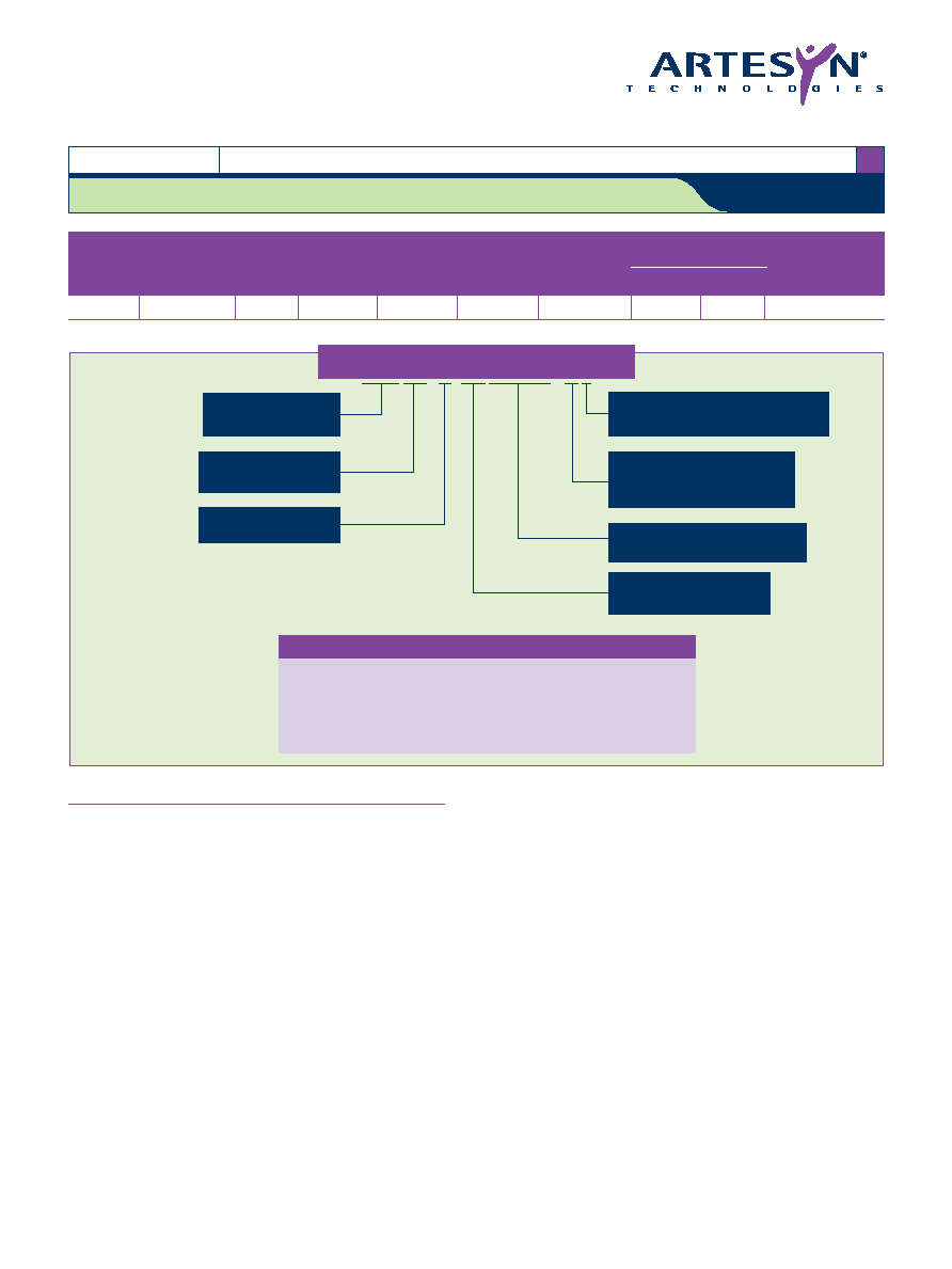
S I L 4 0 C - 1 2 S A D J - V J
Part Number System with Options
Rated Output Current
40 = 40 Amps
Number of Outputs
SADJ = Single Adjustable Output
Product Family
SIL = Single in Line
Performance
C = Cost Optimized
Input Voltage
12 = 10.2 Vdc to 13.8 Vdc
Mounting Option
V = Vertical Mount
H = Horizontal Mount
Packaging Options
J = Pb-free (RoHS 6/6 compliant)
(14)
The ultra-wide output voltage trim range offers major advantages to users who
select the SIL40C-12SADJ series. It is no longer necessary to purchase a
variety of modules in order to cover different output voltages. The output
voltage can be trimmed in a range of 0.9 Vdc to 5.0 Vdc When the SIL40C-
12SADJ series converter leaves the factory the output has been adjusted to
the default voltage of 0.9 V
O
Ou
uttp
pu
utt V
Vo
olltta
ag
ge
e A
Ad
djju
us
sttm
me
en
ntt o
off tth
he
e S
SIIL
L4
40
0C
C--1
12
2S
SA
AD
DJ
J S
Se
erriie
es
s
For the most current data and application support visit www.artesyn.com/powergroup/products.htm
SIL40C Series
1 2 V i n s i n g l e o u t p u t
DC-DC CONVERTERS C Class Non-isolated
3
NEW Product
Datasheet © Artesyn TechnologiesÆ 2005
The information and specifications contained in this datasheet are believed to be correct at time of publication. However, Artesyn Technologies accepts no responsibility for consequences arising
from printing errors or inaccuracies. Specifications are subject to change without notice. No rights under any patent accompany the sale of any such product(s) or information contained herein.
Please consult our website for the following items:
Application Note
Longform Datasheet
www.artesyn.com
File Name: sil40c.pdf Rev (04): 16 Dec 2005
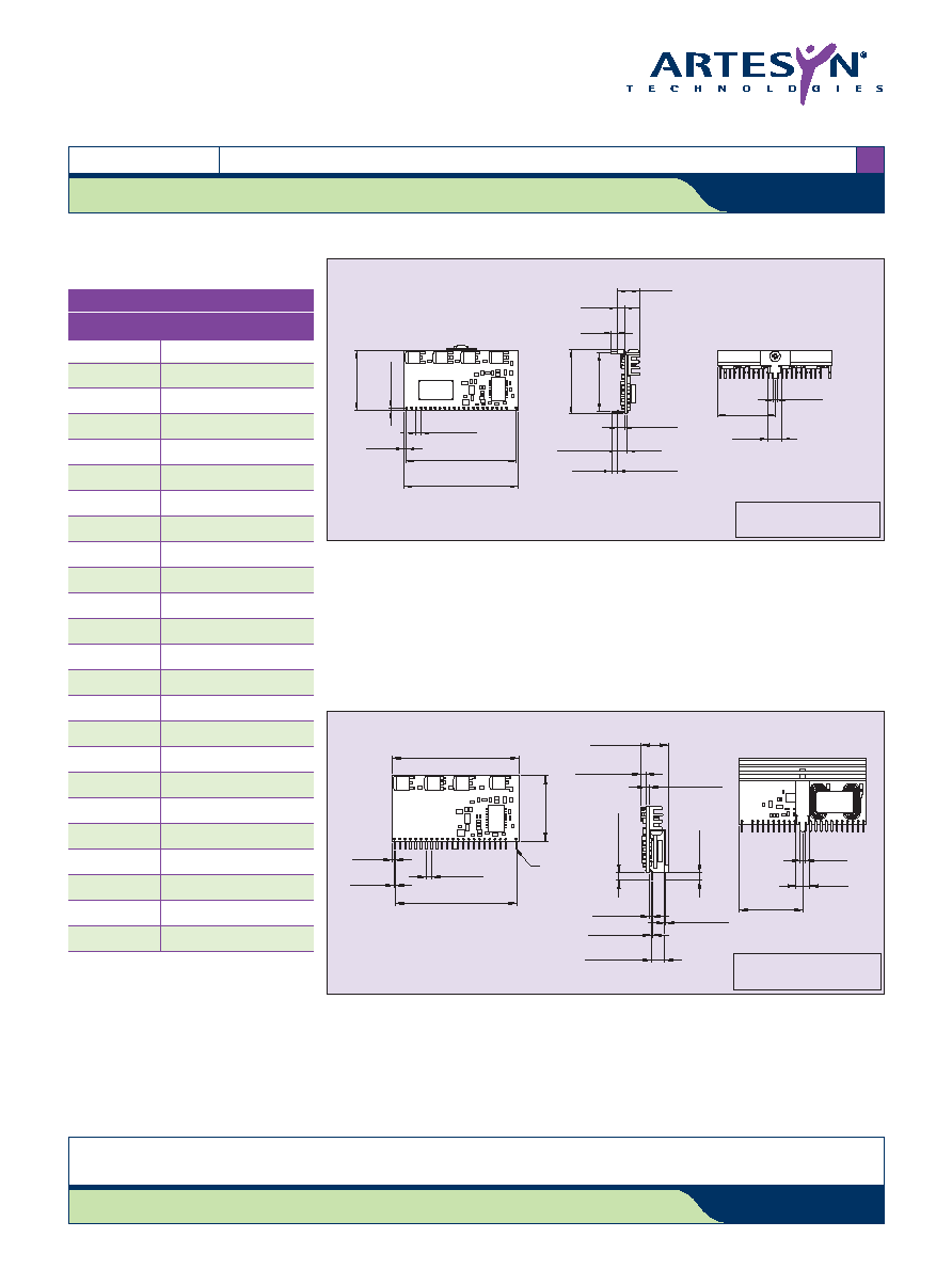
2.300
(58.42)
All dimensions in inches (mm)
General tolerance
±0.015in (±0.30mm)
except where specified otherwise
0.025
±0.001
(0.64) Typ
±0.025
0.050
(1.27)
2.400
(60.96)
1.250
(31.75)
Pin 1
0.100
(2.54) Typ
0.090
(2.29)
0.250
(6.35)
1.200
(30.48)
0.52
±0.02
(13.20
±0.5)
0.025
±0.001
(0.64) Typ
±0.025
0.26
±0.03
(6.591
±0.76)
0.062
(1.57) Ref
0.09
±0.02
(2.4
±0.5)
0.050
(1.27) Typ
0.140
(3.56 T
yp)
0.140
(3.56)
0.019
(0.48) Ref
All dimensions in INCHES (mm)
General tolerance
±0.015in (±0.30mm)
except where specified otherwise
0.470
(11.94)
0.150
(3.82)
0.120
(3.05)
0.150
(3.81) Ref.
0.212
(5.38)
0.120
(3.05)
1.350
(34.36)
1.240
(31.40)
0.090
(2.29)
1.200
(30.48)
0.290
(7.46)
0.100
(2.54) Typ.
2.300
(58.42)
2.400
(60.96)
0.050
(1.27)
0.050
(1.27) Ref.
1.250
(31.75
Figure 1: Mechanical Drawing - Horizontal Mount Version
Figure 2: Mechanical Drawing - Vertical Mount Version
PIN CONNECTIONS
PIN NUMBER
FUNCTION
1
Trim
2
No Pin
3
Ground
4
Power good
5
Not connected
6
Current share
7
Ground
8
Ground
9
Remote ON/OFF
10
Remote sense -
11
Remote sense +
12
Vin
13
Vin
14
Vin
15
Vout
16
Vout
17
Ground
18
Vout
19
Ground
20
Vout
21
Ground
22
Vout
23
Ground
24
Vout