SWG30 SERIES
DC/AC single output ring generator
[ 2 YEAR WARRANTY ]
SPECIFICATION
All specifications are typical at nominal input, full load at 25∞C unless otherwise stated
PAGE 172
∑ 30VA of ringer output power
∑ Short circuit protection
∑ Operating temperature up to 70∞C
∑ Internal sine wave reference
∑ Remote ON/OFF control
Measuring just 4.00 x 4.00 x 0.63 inches, the SWG30 design maximizes
efficiency, typically 80% at full load. Operating from any input voltage in the
range 40 to 60VDC, the SWG30 features indefinite short circuit protection and
overcurrent protection features, and has a high MTBF of 300,000 hours
(calculated in accordance with MIL-HDBK-217F) to ensure reliable operation. A
remote on/off control feature facilitates easy systems integration. The SWG30
ring generator has a typical input current of 780mA, and a maximum output
current of 400mA rms, (260mA peak DC current). The series features line and
load regulation of 1% and at full load the maximum output ripple is typically less
than 5V peak-to-peak. The unit has a wide operating temperature range of 0∞C
to +70∞C and the black coated copper case material meets flammability
standard UL94V-0. The SWG30 has an isolation voltage of 500VDC and an
internal sine-wave reference oscillator.
INPUT NOISE SPECIFICATIONS
Conducted noise
VDE0871, FCC part 15 (Note 7) Level A
GENERAL SPECIFICATIONS
Efficiency
Resistive load
See table
Isolation voltage
500VDC
Switching frequency
Fixed
120kHz, typical
Case material
Black coated copper
Material flammability
UL94V-0
Weight
230g (8.12oz)
MTBF
Demonstrated
300,000 hours
ENVIRONMENTAL SPECIFICATIONS
Thermal performance
Operating temperature
0∞C to +70∞C
ambient Derate
2.5%/∞C
(See Note 1)
after 50∞C, under
Free air convection
cooled
Non-operating
≠40∞C to +85∞C
Cooling
Free air convection
cooled
Relative humidity
Non-condensing
10% to 95% RH
OUTPUT SPECIFICATIONS
Nominal voltage
75VAC, 85VAC, 95VAC
Voltage accuracy
±3.0%
Load regulation (static)
No load to full load
±1.0%
Line regulation
±1.0%
Load impedance
SWG30-48S75C01
188
SWG30-48S85C01
284
SWG30-48S90C01
270
Capacitive load (See Note 2)
30VA
Output frequency
25Hz, ±2Hz
Maximum output current
See table
Output ripple and noise Full load
5V pk-pk
Output ripple frequency Full load
240kHz, nominal
Total harmonic distortion
5.0% max.
Voltage range
±3V
DC offset
±2V max.
INPUT SPECIFICATIONS
Input voltage range
48VDC nominal
40 to 60VDC
Input current
1.1A max. @ 40VDC
Input filter
Pi network
Input undervoltage
48VDC input model
38VDC max.
(output clipped)
Reference input
Internal sine-wave
impedance
reference oscillator
Remote ON/OFF
(See Note 4)
INPUT
OUTPUT
OUTPUT
OUTPUT
PEAK OUTPUT
TYPICAL EFF.
MODEL
VOLTAGE
VOLTAGE
FREQUENCY
CURRENT (RMS)
DC CURRENT
(5)
(MIN)
NUMBER
(4)
48VDC
75VAC
25Hz
400mA
260mA
75%
SWG30-48S75C01
48VDC
85VAC
25Hz
350mA
160mA
70%
SWG30-48S85C01
48VDC
90VAC
25Hz
333mA
180mA
70%
SWG30-48S90C01
Notes
1
The SWG30 can operate up to 70∞C as long as the maximum case
temperature does not exceed 85∞C.
2
The output loading power factor should be greater than 0.85.
3
Measured under resistive load condition at nominal input voltage.
4
All models are available with the suffix `/P' e.g. SWG30-48S75C01/P.
Models with the suffix `/P' have the same specifications as their
corresponding models, except the remote on/off control logic is reversed.
5
Peak output DC current is the DC biased current flowing through the
output. Maximum duration is 1 second.
6
FG pin (pin 5) must be connected to +Vin or -Vin (pins 3 or 4) directly or
through a capacitor greater than 10µF.
7
To meet VDE0871 level A conducted noise, connect a capacitor with a
value >47µF between (+Vin) and (-Vin).
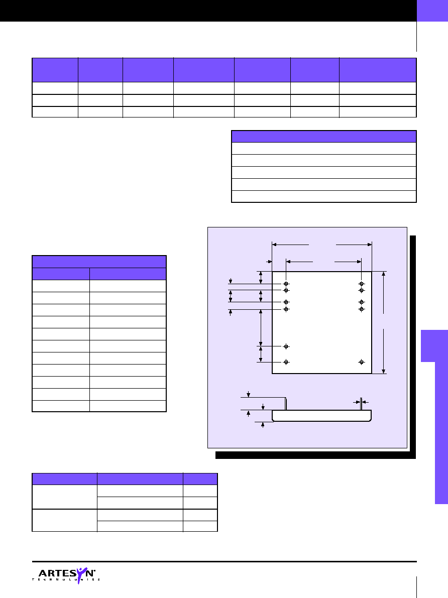
0.63
(16.00)
4.00 Max.
(101.60)
BOTTOM
VIEW
0.40
±
0.05
(10.16)
5
6
11
1
2
3
4
7
8
9
10
3.20
(81.28)
4.00 Max.
(101.60)
ALL DIMENSIONS IN INCHES (mm)
Tolerances unless otherwise specified .xx =
±
0.02
0.236
(5.994)
¯0.04 Dia.
(1.02)
PINS
1-6
PINS
7-11
+0, -0.039
1.80
(45.72)
0.40
(10.16)
0.60
(15.24)
0.20
(5.08)
0.20
(5.08)
0.40
±
0.05
(10.16)
PROTECTION
Short circuit protection
Indefinite
Short circuit input current
48VDC, 120mA max.
Overvoltage protection
None
Overcurrent protection set point
600 to 650mA
Undervoltage protection
None
MODEL
(4)
REMOTE PIN CONNECTION
OUTPUT
SWG30-48SXXC01
Open Circuit
ON
0.4V reference to -Vin
OFF
SWG30-48SXXC01/P
+Vin
ON
Open Circuit
OFF
30VA
DC/AC ring generator
TELEPHONE RING GENERATORS
|
30VA DC/AC
PAGE 173
http://www.artesyn.com
PIN CONNECTIONS
PIN NUMBER
FEATURE
1
+ Vin
2
+ Vin
3
- Vin
4
- Vin
5
FG
(6)
6
Remote ON/OFF
7
+ Vout
8
+ Vout
9
- Vout
10
- Vout
11
No Connection
6

Vin
Vin
1
1
1 +
(1 + R
1
/R
2
)
2
fCR
1
+
2
fCR
2
2
(
)
Fuse
+48Vin
0V
Vout
Return
0V
R
1
R
2
C
Resistive / capacitive loading
power factor =
1
1 +
2
(
)
power factor =
1
2
fCR
Vin
Vin
Fuse
0V
-48Vin
Vout
Return
R
C
capacitive loading
0V
-48Vin
(See note 5 for DC biased current condition)
Vin
Vin
Fuse
+48Vin
0V
Vout
Return
capacitive loading
(See note 5 for DC biased current condition)
R
C
0V
+48Vin
Application notes
1
Examples of DC biased operation.
1.1
Non-biased operation.
1.2
Negative DC Biased operation.
1.3
Positive DC biased operation.
PAGE 174
30VA
DC/AC ring generator
30VA DC/AC |
TELEPHONE RING GENERATORS
Data Sheet © Artesyn TechnologiesÆ 2000
The information and specifications contained in this data sheet are believed to be correct at time of publication. However, Artesyn Technologies accepts no responsibility for consequences arising
from printing errors or inaccuracies. Specifications are subject to change without notice. No rights under any patent accompany the sale of any such product(s) or information contained herein.
DS_SWG30_20000101.PDF