North America (USA): 1-888-41-ASTEC
Europe (UK): 44 (1384) 842-211Asia (HK): 852-2437-9662
2
Electrical Specs
Special Features
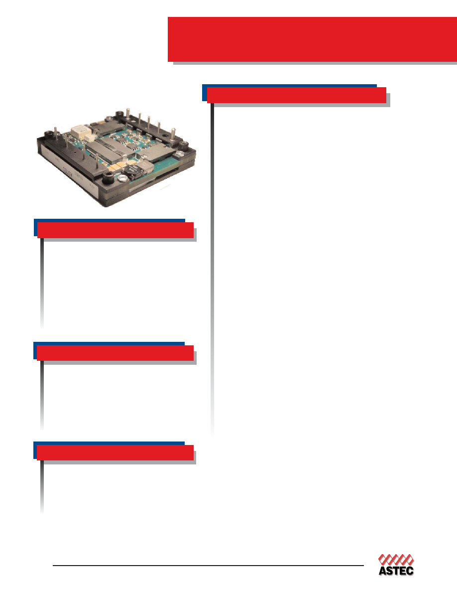
300W
AEH25
Ultra High Efficiency
∑ High efficiency, 12V@ 93% (Typical)
∑ Industry Standard Half Brick baseplate design
∑ Low output ripple and noise
∑ High capacitive load limit on start-up
∑ Remote sense compensation
∑ Regulation to zero load
∑ Fixed frequency switching
∑ Industry Std features: Input UVLO, OCP, OVP,
OTP; Short ckt protection; ±10% Output Adjust
∑ Positive or Negative enable logic control option
∑ Meets Basic Insulation
Environmental
Operating temperature
-40∞C to +100∞C Baseplate
Storage temperature: -55∞C to +125∞C
Overtemperature protection: 110∞C typical
MTBF: >1 million hours
Input
Input range
36-75 VDC
Input Surge
100V / 100ms
Efficiency
93% @ 12V (Typical)
Control
Enable
TTL compatible
(positive or negative enable logic
control options)
Output
Regulation
(Line, Load, Temp)
<2%
Ripple and Noise
1
120mV tyical
Remote Sense
Up to 10%Vout
Output Voltage Adjust
Range
±10% of nominal output
Transient Response
180mV typical output deviation
25% step change
300 µS recovery time
Overvoltage Protection
115% nominal output
Overcurrent Protection
116% Io nominal
Isolation Voltage
1500 Vdc
Safety
UL, cUL 60950 Recognized
TUV
EN60950 Licensed
Total Power:
300 Watts (12V @ 25A)
Input Voltages:
48 V
No. of Outputs:
Single
Astec Industry S
t
andard

EUROPE
Astec House, Waterfront Business Park
Merry Hill, Dudley
West Midlands, DY5 1LX, UK
Telephone: 44 (1384) 842-211
Facsimile: 44 (1384) 843-355
AMERICAS
5810 Van Allen Way
Carlsbad, CA 92008
Telephone: 760-930-4600
Facsimile: 760-930-0698
3
Ordering Information
www.astecpower.com
ASIA
Units 2111-2116, Level 21
Tower1, Metroplaza
223, Hing Fong Road
Fwai Fong, New Territories
Hong Kong
Telephone: 852-2437-9662
Facsimile: 852-2402-4426
Input
Output
Efficiency
Model Number
Voltage
Voltage / Current
36V to 75V
12V @ 25A
93%
AEH25B48(N)-(5)(6)(T)
OPTION: suffix "N"
= Negative Enable
non suffix "N"
= Positive Enable (default)
suffix "-6"
= 3.7mm pin length
suffix "-5"
= 4.5mm pin length
default pin length
= 5mm nominal pin length
suffix "T"
= "Tuned" version for slow start up time
Typical efficiency measurement taken at nominal line, full load, 25∞C ambient.
1
+ Vi
n
1.90
[48.3]
1.50
[38.1]
1.20
[30.4]
0.90
[22.8]
1.90
[48.3]
1.50
[38.2]
1.20
[30.5]
0.90
[22.9]
5
4
2
Enabl
e
(On/Of
f
)
9
+ Out
put
M ECHANI
CAL
TOLERANCE
±
.
002(0.
5)
PI
N
PLACEM ENT
TOLERANCE
:
±
0.
005(0.
127)
ALL
DI
M ENSI
ONS
ARE
I
N
I
NCHES
(M I
LLI
M ETERS)
PI
N
SI
DE
UP
3
2
1
7
6
9
3
CASE
7
Tri
m
8
+ Sense
6
-Sense
5
-Out
put
NOTES:
4
-
Vi
n
PI
N
ASSI
GNM ENT
0.04ÿ
[2.0ÿ] 2 PLACES
PI
N
SI
DE
DOW N
1.90
[48.3]
1.90
[48.3]
2.30
[58.4]
0.50
[12.7]
0.20
[5.1]
0.20
[5.1]
-
Vi
n
+ Vi
n
0.50
[12.7]
M 3 X0.5 M OUNTI
NG HOLE
0.50
[12.7]
4 PLACES
2.40
[61.0]
2.00
[50.8]
-Out
put
+ Out
put
SI
DE
VI
EW
0.46
[11.8]
0.08ÿ
0.20
[5.2]
[1.0ÿ] 7 PLACES
Pin Assignments
Astec Industry S
t
andard
Single Output
1. +Vin
2. Enable (On/Off)
3. Case (AEH)
4. -Vin
5. - Output
6. - Sense
7. Trim
8. + Sense
9. + Output
Notes:
1. 20 MHz BW with external 10uF/25V tantalum in
parallel with 0.1uF/50V X7R ceramic capacitor
placed across the output.
2. Requires a 2.2 uf, 100V film capacitor
connected between +V in and -V in to meet
FCC class A and ETS300-386-1 requirements
for conducted noise. Consult Factory for filtering
information to meet FCC class B, VDE or EIC
specifications.
3. All specifications are typical at nominal line, full
load, and 25∞C unless otherwise noted.
4. All specifications subject to change without
notice. Mechanical drawings are for reference
only
5. Technical Reference Notes should be consulted
for detailed information when available
6. Warranty: 1yr
* Astec reserves the right to make changes to the information
contained herein without notice and assumes no liability as a
result of its use or application. (REV06: JANUARY 26, 2006)
AEH25B48
PIN LENGTH OPTION
"-5": 4.5mm nom
"-6": 3.7mm nom
default is 5mm nom
see A
NOTE:
All dimensions are in Inches [millimeters]
Pin Placement Tolerance: ± 0.005 [0.127]
Mechanical Tolerance: ± 0.002 [0.5]