
33
www.ptcc.com.tw
AS1004
Micropower Voltage Reference
SEMICONDUCTOR
Features
∑
Low voltage reference
∑
10 µA turn-on current for AS1004-1.2
∑
20 µA turn-on current for AS1004-2.5
∑
± 4 mV (0.3%) initial accuracy for
AS1004-1.2
∑
± 20 mV (0.8%) initial accuracy for
AS1004-2.5
∑
Guaranteed operation to 20 mA. Over
three orders of magnitude of operating
current!
∑
Temperature performance guaranteed
∑
Very low dynamic impedance
Description
The AS1004 is a two-terminal precision bandgap voltage reference
with a low turn-on current of 10 µA.
Emulating a 1.235 V zener diode, the AS1004 operates more than
three orders of magnitude of output current with minute output imped-
ance and guaranteed stability. With an initial tolerance of ± 4 mV and
guaranteed temperature performance, it is ideal for precision instru-
mentation, especially in low power applications. Being a low-voltage
reference, the AS1004 is also well-suited as a reference for low-volt-
age power supply applications, especially in power supplies intended
for low-voltage logic systems, laptop computers and other portable or
battery operated equipment.
The AS1004 is pin-for-pin compatible with the LT1004 and the LM385
and offers improved specifications over both the LM385 and the
MP5010. It is also available as a 2.5 V reference with a guaranteed
start-up current of 20 µA.
Pin Configuration --
Top view
Ordering Information
ANODE
TO-92 (LP)
8L SOIC (8D)
CATHODE
N/C
N/C
CATHODE
N/C
CATHODE
ANODE
N/C
N/C
N/C
ANODE
SOT-89 (S)
ANODE
CATHODE
1
2
3
4
8
7
6
5
Circuit Type:
Micropower Voltage Reference
Reference Voltage:
A = 1.235V
B = 2.50V
Temperature Range:
A = 0
∞
C to 70
∞
C
Packaging Option:
A
B
T
N
Package Style:
8D
LP
S
= Ammo Pack
= Bulk
= Tube
= Tape and Reel (13" Reel Dia)
= 8 Pin, Plastic SOIC
= TO-92
= SOT-89
AS1004 A A 8D N
34
www.ptcc.com.tw
AS1004
Micropower Voltage Reference
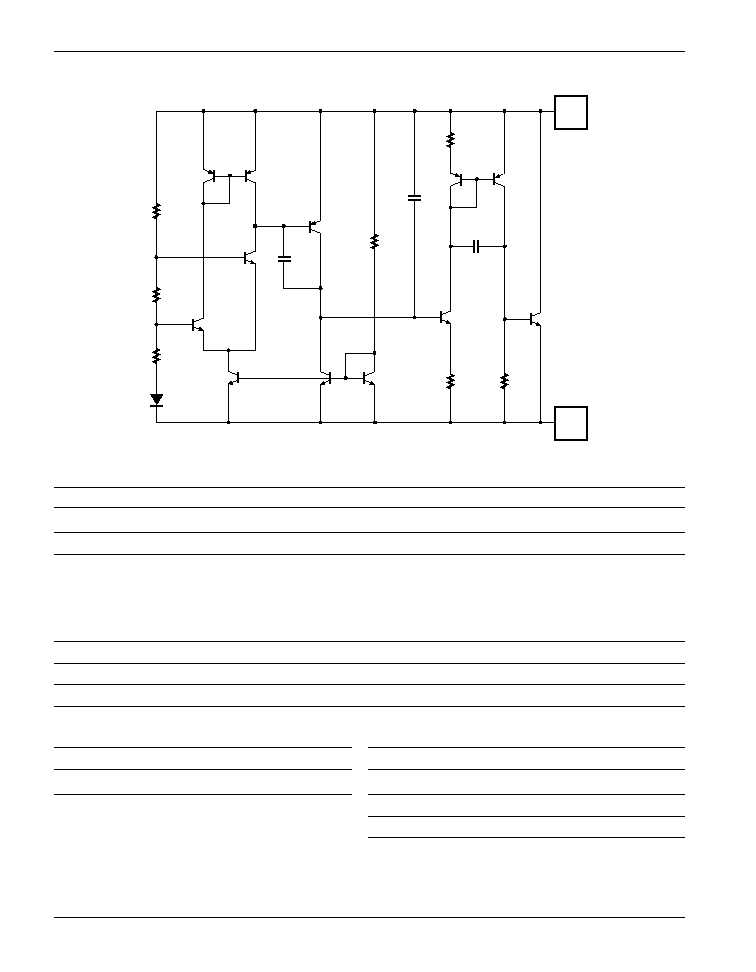
Simplified Schematic
Q13
Q12
R10
R11
R12
Q14
Q9
Q10
Q11
C3
Q7
R4
C2
Q4
R2
Q3
C1
Q1
Q5
R6
R7
Q8
Q6
K
A
Absolute Maximum Ratings
Parameter
Symbol
Rating
Units
Reverse Breakdown Current
I
Z
30
mA
Forward Current
I
F
30
mA
Continuous Power Dissipation at 25∞C
P
D
TO-92
775
mW
8L SOIC
750
mW
SOT-89
1000
mW
Maximum Junction Temperature
T
J
150
∞C
Storage Temperature
T
STG
≠65 to 150
∞C
Lead Temperature, Soldering 10 Seconds
T
L
300
∞C
Recommended Conditions
Parameter
Symbol
Rating
Unit
Cathode Current
I
Z
100
µA
Typical Thermal Resistances
Package
JA
JC
Typical Derating
TO-92
160∞C/W
80∞C/W
6.3 mW/∞C
8L SOIC
175∞C/W
45∞C/W
5.7 mW/∞C
SOT-89
110∞C/W
8∞C/W
9.1 mW/∞C
35
www.ptcc.com.tw
AS1004
Micropower Voltage Reference
Electrical Characteristics
Electrical Characteristics are guaranteed over full junction temperature range (0 to 70∞C). Ambient temperature must be derated
based on power dissipation and package thermal characteristics.
AS1004-1.2
AS1004-2.5
Parameter
Symbol
Test Condition
Min.
Typ.
Max.
Min.
Typ.
Max.
Unit
Reverse Breakdown Voltage
V
Z
I
Z
= 100 µA, T
J
= 25∞C
1.231
1.235
1.239
2.480
2.500
2.520
V
0∞C
T
A
70∞C
1.225
1.235
1.245
2.470
2.500
2.530
V
Average Temperature
V
Z
/
T
I
min
I
Z
20 mA
20
60
ppm/∞C
Coefficient
Minimum Operating Current
I
Z (min)
4
10
12
20
µA
Reverse Breakdown Voltage
V
Z
/
I
Z
I
min
I
Z
1 mA
0.5
1
0.5
1
mV
Change With Current
Over Temperature
0.5
1.5
0.5
1.5
mV
1 mA
I
Z
20 mA
6.5
10
6.5
10
mV
Over Temperature
6.5
20
6.5
20
mV
Reverse Dynamic Impedance
Z
Z
I
Z
= 100 mA, f = 25 Hz
0.2
0.6
0.8
0.9
Over Temperature
1
1.5
1.5
Wide Band Noise
e
n
I
Z
= 100 µA
10 Hz
f
10 KHz
60
60
µV
Long Term Stability
V
Z
/
T
I
Z
= 100 µA
T
A
= 25∞C ± 0.1∞C
20
60
ppm/kH
0
0
≠5
≠10
5000
0.5
0
10
0.025 mV/
∞
C
0.002%/
∞
C
20 ppm/
∞
C
30
20
60
50
40
70
ppm
mV
%
V
REF
T
T
V
REF
Temperature (
∞
C)
0
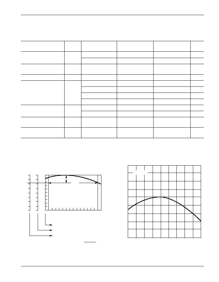
Average Temperature Coefficient =
Calculating Average Temperature
Coefficient for the AS1004-1.2 Reference
≠55
≠35
≠15
5
25
T
A
≠ Ambient Temperature (
∞
C)
45
65
85
105
125
1.245
1.240
1.235
V
Z
≠ Reference V
oltage (V)
1.230
1.225
AS1004-1.2 Reference Voltage vs. Ambient Temperature
I
Z
= 100
µ
A
Typical Performance Curves
Figure 1
Figure 2
36
www.ptcc.com.tw
AS1004
Micropower Voltage Reference
0
0
≠5
≠10
5000
0.5
0
10
0.046 mV/
∞
C
0.004%/
∞
C
37 ppm/
∞
C
30
20
60
50
40
70
ppm
mV
%
V
REF
T
T
V
REF
Temperature (
∞
C)
0
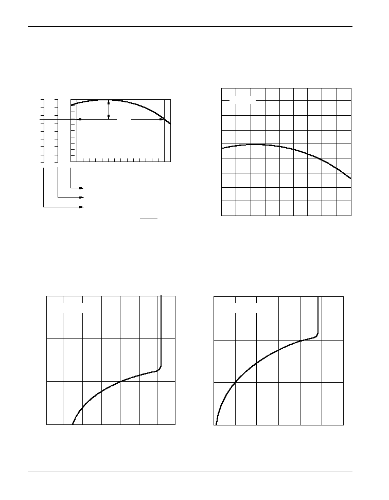
Average Temperature Coefficient =
Calculating Average Temperature
Coefficient for the AS1004-2.5 Reference
≠55
≠35
≠15
5
25
T
A
≠ Ambient Temperature (
∞
C)
45
65
85
105
125
2.52
2.51
2.50
V
Z
≠ Reference V
oltage (V)
2.49
2.48
AS1004-2.5 Reference Voltage
versus Ambient Temperature
I
Z
= 100
µ
A
0
0.2
0.4
0.6
0.8
1.0
1.2
1.4
V
R
≠ Reverse Voltage (V)
I
R
≠ Reverse Current (
µ
A)
0.1
1
10
100
AS1004-1.2 Reverse Operating Characteristics
T
A
= ≠55
∞
C to 125
∞
C
0
0.5
1.0
1.5
2.0
2.5
3.0
V
R
≠ Reverse Voltage (V)
0.1
1
10
100
I
R
≠ Reverse Current (
µ
A)
AS1004-2.5 Reverse Operating Characteristics
T
A
= ≠55
∞
C to 125
∞
C
Typical Performance Curves
Figure 3
Figure 4
Figure 5
Figure 6

37
www.ptcc.com.tw
AS1004
Micropower Voltage Reference
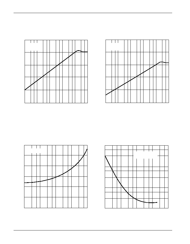
0.01
0.1
1
10
100
≠4
0
4
8
12
16
I
R
≠ Reverse Current (mA)
AS1004-1.2 Change in Reference
Voltage versus Reverse Current
V
z ≠ Change in Reference V
oltage (mA)
T
A
= ≠55
∞
C to 125
∞
C
I
R
≠ Reverse Current (mA)
0.01
0.1
1
10
100
≠4
0
4
8
12
16
AS1004-2.5 Change in Reference
Voltage versus Reverse Current
V
z ≠ Change in Reference V
oltage (mA)
T
A
= ≠55
∞
C to 125
∞
C
0
50
t ≠ Time (
µ
s)
100
500
600
0
5
0
0.5
1.0
1.5
36 k
V
O
V
I
OUTPUT
INPUT
AS1004-1.2 Transient Response
Input and Output V
oltage (V)
0
50
t ≠ Time (
µ
s)
100
500
600
OUTPUT
INPUT
AS1004-2.5 Transient Response
0
5
0
1
2
3
Input and Output V
oltage (V)
V
O
V
I
36 k
Typical Performance Curves
Figure 7
Figure 8
Figure 9
Figure 10
38
www.ptcc.com.tw
AS1004
Micropower Voltage Reference
0.01
0.1
1
10
100
1 k
10 k
1 k
100
10
1
0.1
Z
Z
≠ Reference Impedance (
)
f = Frequency (kHz)
t
Z
= 100
µ
A
T
A
= 25
∞
C
AS1004-1.2 Reverse Dynamic Impedance
Z
Z
≠ Reference Impedance (
)
AS1004-2.5 Reverse Dynamic Impedance
0.01
0.1
1
10
100
1 k
10 k
1 k
100
10
1
0.1
f = Frequency (kHz)
t
Z
= 100
µ
A
T
A
= 25
∞
C
Forward Characteristics
0.01
0.1
1
10
100
I
F
= Forward Current (mA)
1.2
0.8
0.4
0
V
F
≠ For
ward V
oltage (V)
T
A
= 25
∞
C
Z
Z
≠ Reference Impedance (
)
0.01
0.1
1
10
100
I
Z
≠ Reverse Current (mA)
100
Low Frequency Reverse Dynamic Impedance
10
1
0.1
T
A
= ≠55
∞
C to 125
∞
C
f = 25 Hz
Typical Performance Curves
Figure 11
Figure 12
Figure 13
Figure 14
39
www.ptcc.com.tw
AS1004
Micropower Voltage Reference
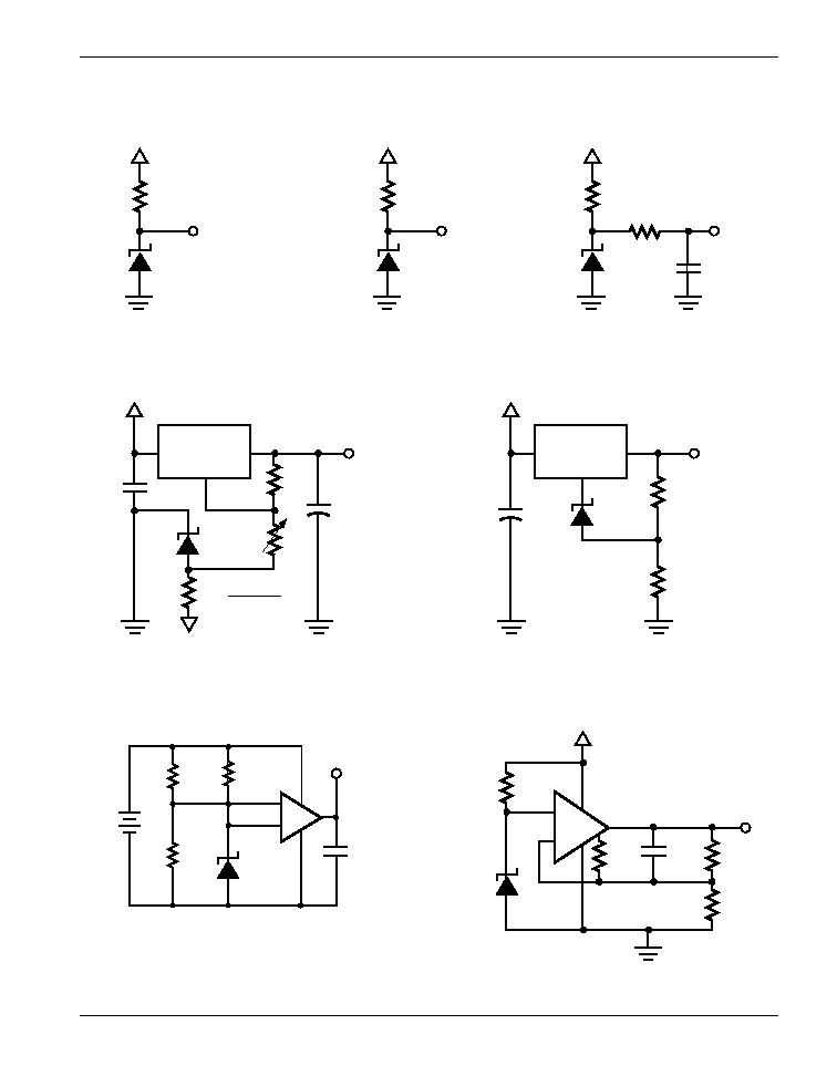
Typical Applications
+
≠
3 k
V
IN
OUT
AS1004-1.2
Figure 15
100 k
V
IN
OUT
AS1004-2.5
Figure 16
1.235V Reference
2.5V Reference
100 k
V
IN
AS1004-2.5
Figure 17
Low Noise Reference
12 V
86.7 k
500 k
500 k
AS1004-1.2
LO = Battery Low
150 pF
Lead Acid Low Battery Detector
Micropower 10V Reference
LM338
AS1004-2.5
ADJ
V
IN
V
IN
8 V
V
IN
= 12 V to 20 V
R
V
≠
22
µ
F
V
OUT
5 V OUT
976
, 1%
324
, 1%
Figure 19
+
High Stability 5V Regulator
LM317
AS1004-2.5
ADJ
V
IN
V
IN
10
µ
F
0.1
µ
F
50
µ
F
V
OUT
OUT
200
Figure 18
Figure 21
Figure 20
+
Variable Output Regulator
5 k
V
≠
≠ 1V
0.015 mA
LM4250
+
≠
AS1004-1.2
1 M
7
3
2
4
8
6
22 M
150 pF
3.5 M
500 k
OUT