 | –≠–ª–µ–∫—Ç—Ä–æ–Ω–Ω—ã–π –∫–æ–º–ø–æ–Ω–µ–Ω—Ç: AS273 | –°–∫–∞—á–∞—Ç—å:  PDF PDF  ZIP ZIP |
111
www.ptcc.com.tw
AS273
Over-Temperature Dectector
SEMICONDUCTOR
Features
∑
Programmable to three different
over-temperature thresholds
∑
2.5 V temperature compensated
bandgap reference trimmed to
1%
∑
Open collector output goes low
on over-temp condition
∑
±3∞C temperature accuracy
∑
Reference shunt current serves
to program over-temp threshold
∑
Available with 5∞C or 10∞C of
temperature hysteresis
∑
Available in a wide range of
over-temp thresholds to fit most
temperature monitoring
applications
∑
Now available in the SOT-223 for
improved substrate temperature
sensing
Description
The AS273 is a series of programmable over-temperature detectors.
Each is internally composed of a precision 2.5 V shunt reference, a pro-
portional-to-absolute temperature thermal sensor, a comparator with
controlled hysteresis, and an open collector output that indicates an
over-temp condition. The threshold for the over-temp signal can be set
to any of three values on a given part by controlling the magnitude of
the reference shunt current.
The AS273 has an excellent absolute temperature accuracy of ±3∞C for
each of the three over-temp thresholds. The low power dissipation min-
imizes any temperature sensing errors due to self-heating. There is
either 5∞C or 10∞C of temperature hysteresis to prevent bouncing when
an over-temp condition is removed.
The packaging options available with the AS273 make it appealing to a
wide variety of temperature-sensing applications. The TO-92 package
can be mechanically clamped to a heat sink to monitor the temperature
of power devices. The 8L-SOIC and SOT-223 surface mount packages
allow for temperature sensing in high component density applications
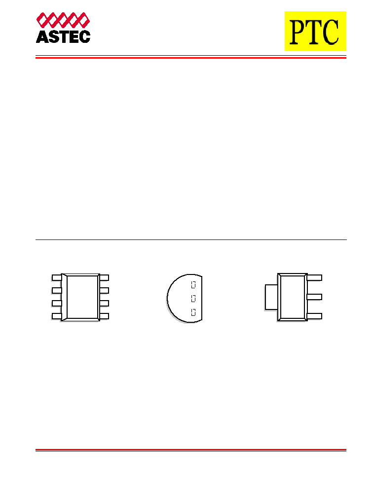
Pin Configuration --
Top view
OUT
TO-92 (LP)
SOT-223 (G)
GROUND
V
REF
OUT
GROUND
V
REF
SOIC (D)
VREF
DO NOT USE
DO NOT USE
GROUND
OUT
N/C
N/C
N/C
1
2
3
4
8
7
6
5
112
www.ptcc.com.tw
AS273
Over-Temperature Detector
Ordering Information
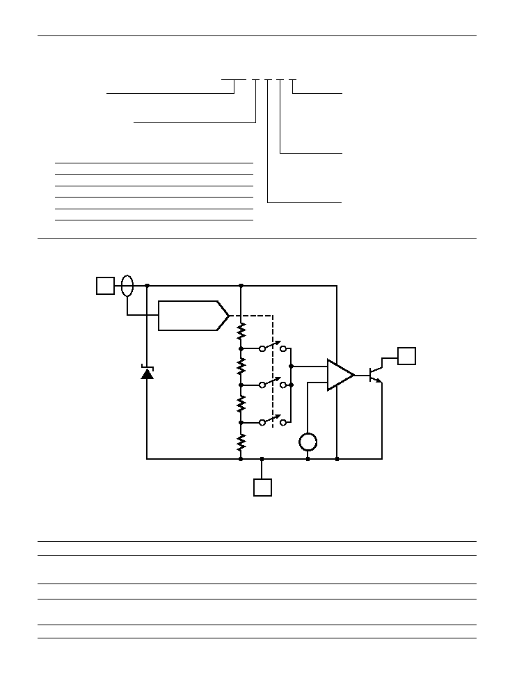
Functional Block Diagram
Pin Function Description
Pin Number
Function
Description
1
VREF
2.5 V shunt reference; current into VREF pin also programs
over-temperature trip point to one of three TOT values
2
GND
Circuit ground and silicon substrate
3
OUT
Open collector output. Output low when die temperature exceeds
programmed trip point
Circuit Type:
Over-Temperature Detector
Temperature Option:
(Refer to Table A)
Packaging Option:
A
B
T
N
Package Style:
D
G
LP
Hysteresis Option:
1
2
= Ammo Pack
= Bulk
= Tube
= Tape and Reel (13" Reel Dia)
= SOIC
= SOT-223
= TO-92
= 10
∞
C
= 5
∞
C
AS273 D 1 D A
≠
+
CURRENT
PROGRAMMING
1
3
2
V
REF
2.5 V
+
≠
GND
OUT
4 mV/K
Table A ≠ Temperature Options
Code
TOT1
TOT2
TOT3
D
40
45
50
F
75
80
85
G
90
95
100
H
105
110
115

113
www.ptcc.com.tw
AS273
Over-Temperature Detector
Absolute Maximum Ratings
Parameter
Symbol
Rating
Unit
Reference Current
VREF
±
10
mA
Output Current
IOUT
±
10
mA
Output Voltage
VOUT
18
V
Continuous Power Dissipation at 25∞C
TO-92
PD
775
mW
8-SOIC
PD
750
mW
SOT-223
PD
1000
mW
Junction Temperature
TJ
150
∞C
Storage Temperature
TSTG
≠65 to 150
∞C
Lead Temp, Soldering 10 Seconds
TL
300
∞C
Stresses greater than those listed under ABSOLUTE MAXIMUM RATINGS may cause permanent damage to the device. This is a
stress rating only and functional operation of the device at these or any other conditions above those indicated in the operational sec-
tions of this specification is not implied. Exposure to absolute maximum rating conditions for extended periods may affect reliability.
Typical Thermal Resistances
Package
JA
JC
Typical Derating
SOT-223
115∞C/W
8∞C/W
8.7 mW/∞C
TO-92
160∞C/W
80∞C/W
6.3 mW/∞C
8L SOIC
175∞C/W
45∞C/W
5.7 mW/∞C
114
www.ptcc.com.tw
AS273
Over-Temperature Detector
Electrical Characteristics
Electrical Characteristics are guaranteed over the full junction temperature range (0 to 125∞C). Ambient temperature must be derated
based upon power dissipation and package thermal characteristics.
Parameter
Symbol
Test Condition
Min.
Typ.
Max.
Unit
Reference
Reference Voltage
VREF
IREF = 2 mA, TJ = 25∞C
2.500
2.525
2.550
V
Load Regulation
VId
0.65 mA
IREF
5.5 mA
5
10
mV
Average Temperature Coefficient
VREG/
T 0.65 mA
IREF
5.5 mA
75
ppm/∞C
Output
Saturation Voltage
VOL
IOUT = 4 mA; TJ > TOT
200
400
mV
Breakdown Voltage
BV
IOUT = 100
µ
A; TJ < TOT
18
30
V
Leakage Current
IOH
VOUT = 18 V; TJ < TOT
1
1000
nA
Over-Temp Sensing
Temperature Accuracy
TOT(1)
0.7 mA
IREF
1.3 mA
≠3
+3
∞C
TOT(2)
1.55 mA
IREF
2.6 mA
≠3
+3
∞C
TOT(3)
3.0 mA
IREF
5.0 mA
≠3
+3
∞C
Hysteresis
HOT
Percentage Error in Nominal Hysteresis
≠30
+30
%
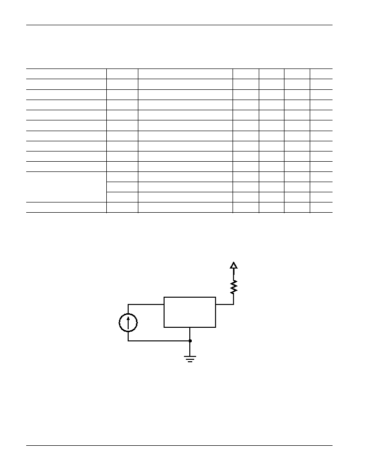
+5V
I
REF
OUT
V
REF
GND
AS273
R
LOAD
2 k
Test Circuit
Figure 1. Test Circuit for Output Hysteresis Curve
115
www.ptcc.com.tw
AS273
Over-Temperature Detector
0
25
50
75
100
125
150
300
275
250
225
200
175
150
125
100
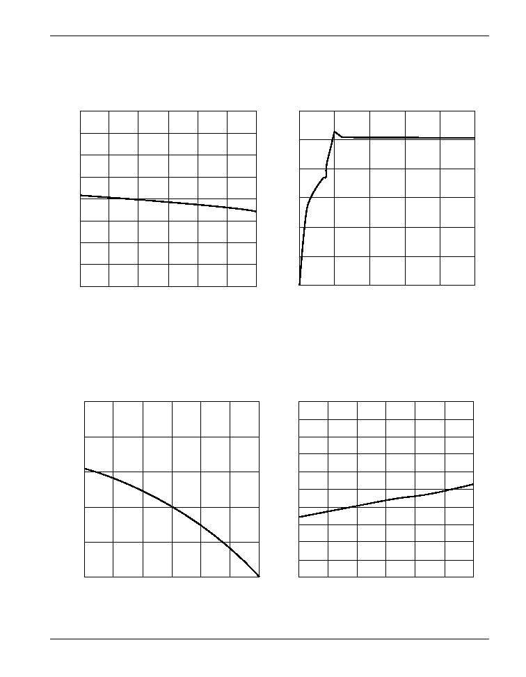
Minimum Reference Current for Regulation
Junction Temperature, T
J
(
∞
C)
T
urn-on Current, I
REF
(
µ
A)
0
200
400
600
800
1000
3
2
1
0
Turn-on Characteristic of Reference
Reference Current, I
REF
(
µ
A)
Reference V
oltage, V
REF
(V)
0
25
50
75
Junction Temperature, T
J
(
∞
C)
100
125
150
2.55
2.54
2.53
2.52
2.51
2.50
Temperature Regulation of Reference
Reference V
oltage, V
REF
(V)
0
25
50
75
Junction Temperature, T
J
(
∞
C)
100
125
150
10
9
8
7
6
5
4
3
2
1
0
Load Regulation of Reference Over-temperature
Load Regulation (mV)
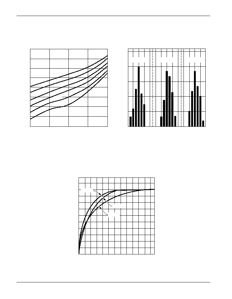
Typical Performance Curves
Figure 2
Figure 3
Figure 4
Figure 5
116
www.ptcc.com.tw
AS273
Over-Temperature Detector
0.001
0.01
0.1
1
10
900
800
700
600
500
400
300
200
100
Output Saturation Characteristic
Output V
oltage, V
OUT
(mV)
125
∞
C
100
∞
C
75
∞
C
50
∞
C
25
∞
C
0
∞
C
Saturation Current, I
OUT
(mA)
88
90
92
94
Over-temperature Threshold (
∞
C)
96
98
100
102
0
10
20
30
40
50
I
REF
= 1 mA
I
REF
= 2 mA
I
REF
= 4 mA
Typical Over-temperature Threshold Distribution ≠ Option G
Distribution of Population (%)
0
2
4
6
8
10
12
120
100
80
60
40
20
0
8L SOIC
TO-92
SOT-223
Time (s)
Per
cent of Thermal Equilibrium (%)
Thermal Response by Package in a Stirred Oil Bath
Typical Performance Curves
Figure 6
Figure 7
Figure 8
117
www.ptcc.com.tw
Theory of Operation
The AS273 is an over-temperature detector that
gives an over-temp signal when the device
junction temperature exceeds a programmed
over-temp threshold. Over-temp threshold pro-
gramming is accomplished by controlling the
magnitude of the reference shunt current.
Over-temperature Condition
Internal to the AS273 is a temperature sensor
which creates a voltage proportional to the
absolute temperature (PTAT) of the die. This
PTAT voltage is compared with a fraction of the
reference voltage corresponding to the over-
temperature threshold. When the PTAT voltage
exceeds the reference voltage, the comparator is
tripped and an over-temp signal is given to the
output. The output consists of an open collector
transistor that pulls low on an over-temp condi-
tion. Built into the comparator is temperature hys-
teresis, which keeps the over-temp signal until
the junction temperature has fallen 5∞C (or 10∞C)
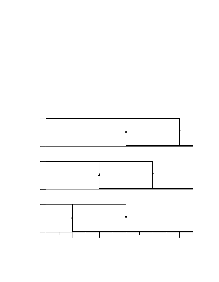
below the over-temp threshold. Figure 9 shows
the output of the AS273 (with 10∞C of hysteresis)
over a range of junction temperature.
AS273
Over-Temperature Detector
Figure 9. Temperature Characteristic of Output with 10∞C of Hysteresis
5
0
I
REF
= 4 mA
5
0
I
REF
= 2 mA
5
0
I
REF
= 1 mA
OT1
OT2
OT3
OT1-5
OT1-10
Output Voltage, V
Junction Temperature, T
J
(
∞
C)
118
www.ptcc.com.tw
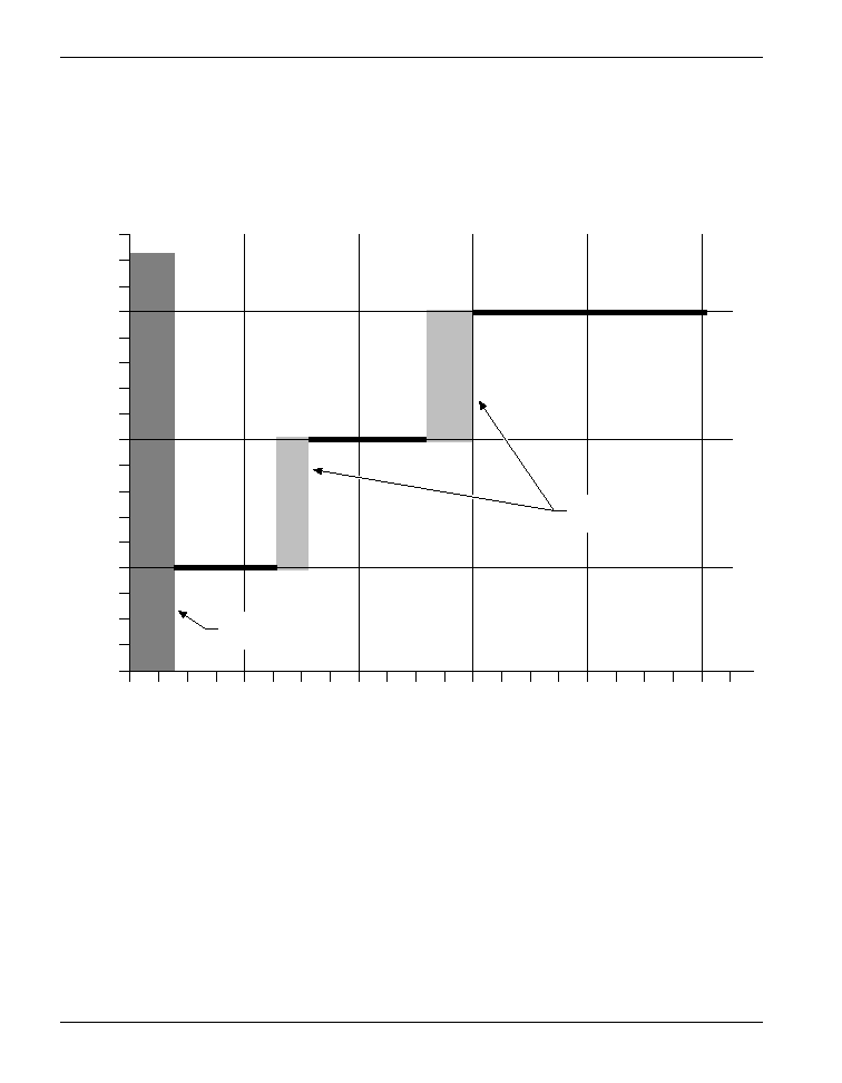
There are three different over-temp thresholds
for each AS273. The detector senses the amount
of current being shunted through the 2.5 V refer-
ence of pin 1 and programs an over-temp thresh-
old based on the magnitude of that current.
Figure 10 illustrates the ranges of reference
shunt current, IREF, associated with each of the
three over-temp thresholds, OT1, OT2 and OT3.
AS273
Over-Temperature Detector
Figure 10. Reference Shunt Current Programming Ranges of Over-temperature Thresholds
OT3
OT2
OT1
0
1
2
3
4
5
Over-temperature Thresholds (
∞
C)
Reference Shunt Current, I
REF
(mA)
Output Disabled
Transition Regions
Current Programming
119
www.ptcc.com.tw
Typical Detector Applications
Over-Temperature Detector
The AS273 senses the ambient temperature and
turns on its open collector output to indicate an
over-temp condition. Each AS273 can be pro-
grammed to any one of its three over-temp
thresholds by forcing a different range of current
into the reference pin.
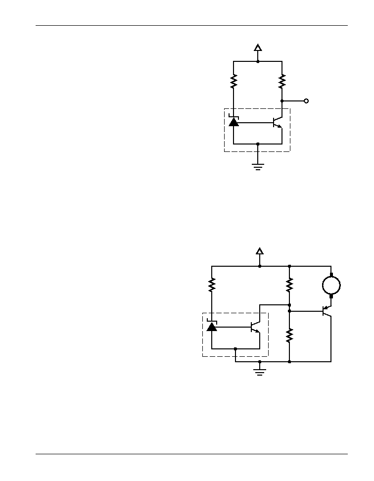
Dual Speed Fan Control
The diagram of Figure 12 shows an easy way to
implement smart fan control. When the tempera-
ture is below the over-temp trip point set by R1,
the detector's open collector output is off.
Therefore, the fan speed is controlled by the ratio
between R2 and R3. When the temperature
exceeds the over-temp set point, the open col-
lector is turned on, and fan motor runs at its full
speed.
AS273
Over-Temperature Detector
Figure 11
Figure 12
V
CC
R2
R1
V
OUT
REF
OUT
GND
AS273
+12 V
R1
9.1 k
REF
OUT
GND
AS273
R2
10 k
R3
10 k
Q1
M
120
www.ptcc.com.tw
AS273
Over-Temperature Detector
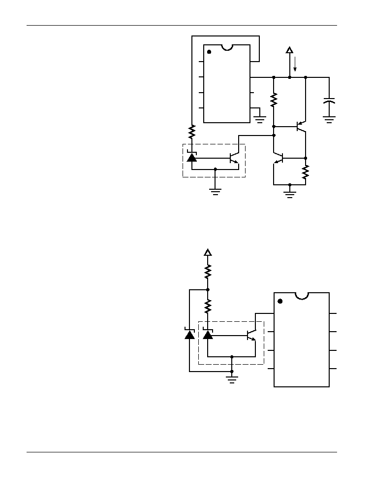
Over-Temperature Protection with
Latch (Low Current)
The diagram of Figure 13 illustrates how a power
supply can be shut down with a simple two-
transistor latch. When the programmed over-
temp is reached, the open collector output of the
AS273 enables the latch and pulls VCC below
the under-voltage threshold of the AS3842, shut-
ting off the AS3842. The latch can be disabled
only with a power reset.
Over-Temperature Protection with
Hysteresis
In this over-temperature circuit, the hysteresis of
the AS273 is used to automatically restart the
power supply after the temperature drops below
the hysteresis temperature window. R1 supplies
the current to power the AS273 after the AS3842
and the power supply are shut down. R2 and
the external zener set the over-temperature trip
point.
Figure 13
Figure 14
V
CC
I
CC
= 400 mA
MAX.
REF
OUT
GND
AS273
COMP
V
REG
V
FB
V
CC
SENSE
OUT
RT/CT
GND
AS3842
R1
1 k
R3
350
+
R2
350
V BULK
R1
REF
OUT
GND
AS273
R2
COMP
V
REG
V
FB
V
CC
SENSE
OUT
RT/CT
GND
AS3842
121
www.ptcc.com.tw
AS273
Over-Temperature Detector
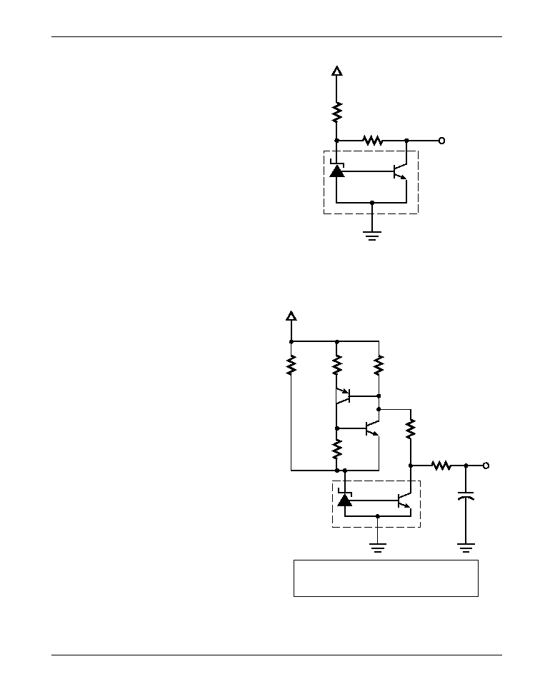
Adjustable Hysteresis Temperature
Detector
The hysteresis of the AS273 can be increased by
reprogramming the device to a lower tempera-
ture set point upon over-temp. A higher tempera-
ture is set by R1. When the temperature exceeds
the high-temp set point, the open collector output
is turned on and allows R2 to rob current from the
reference pin and resets the AS273 to the low-
temp set point. As a result, the hysteresis esca-
lates by the difference between the high-temp
and the low-temp set points.
Three-State Temperature Sensor
In the Three-State Temperature Sensor shown in
Figure 16, a low-temp trip point is selected by R1
and a high-temp trip point is selected by the two-
transistor latch. When the temperature is below
the low-temp set point, VOUT is in the high state
(VOUT = 5.0 V). When the temperature exceeds
the low-temp set point, the two-transistor latch is
set and VOUT is pulled low (VOUT = 2.5 V). The
latch also supplies extra current to the reference
pin to reset the IC to sense a higher temperature.
Once the high-temp is reached, the output will
turn "on" (VOUT = 0.2 V). This circuit is highly
useful in applications where a stand-by, a warn-
ing and a shut-down state are required.
Figure 15
Figure 16
V
CC
R2
R1
V
OUT
REF
OUT
GND
AS273
V
CC
+5 V
R1
2.4 k
REF
OUT
GND
AS273
R2
1 k
R3
1.5 k
R5
2 k
R4
470
R6
500
+
V
O
C1
1
µ
F
Stand-by State:
Warning State:
Shut-down State:
T < T1, T2
T1 < T < T2
T1, T2 < T
V
O
= 5.0 V
V
O
= 2.5 V
V
O
= 0.2 V

122
www.ptcc.com.tw
AS273
Over-Temperature Detector
Notes