 | ÐлекÑÑоннÑй компоненÑ: DS850-3 | СкаÑаÑÑ:  PDF PDF  ZIP ZIP |
Äîêóìåíòàöèÿ è îïèñàíèÿ www.docs.chipfind.ru
Rev. 03.13.06
DS850-3
1 of 4
Embedded Power for
Business-Critical Continuity
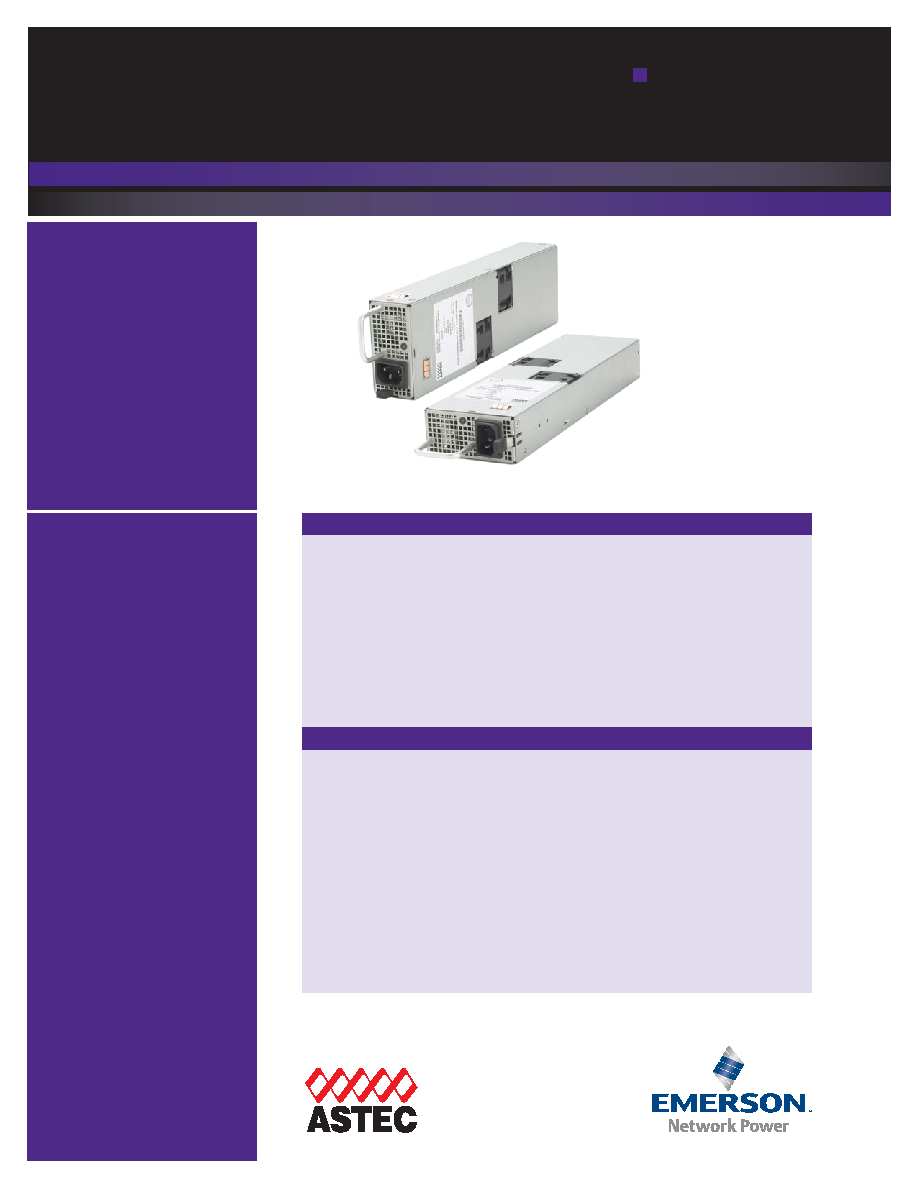
DS850-3
850 Watts 12V
Distributed Power System
Special Features
· Active Power Factor Correction
· EN61000-3-2 Harmonic
Compliance
· Active AC Inrush Control
· 1U X 2U Form Factor
· 15.4W/ in
3
· +12Vdc Output
· +3.3vdc Stand-By
(5V standby - consult factory)
· No Minimum Load Required
· Hot Plug Operation
· N + 1 Redundant
· Internal OR'ing Fets
· Active Current Sharing
(10 - 100% load)
· Built-in Cooling Fans
(40mm x 28mm)
· I
2
C Communication Interface Bus
· EERPOM for FRU Data
· Red/Green Bi-Color LED Status
· Internal Fan Speed Control
· Fan Fail Tach Output Signal
· INTEL, SSI Std. Logic Timing
· INTEL, SSI Std. FRU Data Format
· One Year Warranty
Distributed Power Bulk Front-End
Total Output Power: 850 Watts
+3.3vdc Stand-by Output
Wide Range Input voltage: 90 - 264VAC
Electrical Specifications
Safety
Input
Input range
90-264 VAC (wide range)
Frequency
47-63 Hz, single phase AC
Inrush current
55A maximum inrush current
Efficiency
>82% typical at full load, high line
Conducted EMI
FCC Subpart J EN55022 Class B
Radiated EMI
FCC Subpart J EN55022 Class B
Power factor
0.99 typical
Leakage current
1.40mA @ 240VAC
Hold up time
20ms minimum
Output
Main DC voltage
+12V @ 70A
Stand-By
+3.3vsb @ 6A (5V @ 4A available)
Adjustment range
Factory Set, no pot adjustments
Regulation
+12Vdc; +5%/-5%
+3.3vsb; +5%/-5%
Over current
+12Vdc; 77A - 105A latches off if overcurrent lasts over
1 second, otherwise it is auto recovery.
+3.3vsb, 9A max (hiccup mode)
Over voltage
+12Vdc; 13.2 - 14.4vdc
+3.3vsb; 3.76 - 4.30vdc
Under voltage
+12Vdc; 9 - 10.8V (latch off)
Turn-on delay
2 Second max, 5 - 50mS, Monotonic Rise
+12VOutput Rise Time
5 - 50mS, Monotonic Rise
UL/cUL 60950 (UL Recognized)
NEMKO+ CB Report EN60950
EN60950
CE Mark
China CCC

Rev. 03.13.06
DS850-3
2 of 4
Embedded Power for
Business-Critical Continuity
Ordering Information
O
Ou
uttp
pu
utt
N
No
om
miin
na
all O
Ou
uttp
pu
utt
V
Vo
olltta
ag
ge
e S
Se
ett P
Po
oiin
ntt
S
Se
ett P
Po
oiin
ntt
T
To
olle
erra
an
ncce
e
T
To
otta
all
R
Re
eg
gu
ulla
attiio
on
n
M
Miin
niim
mu
um
m
C
Cu
urrrre
en
ntt
M
Ma
axxiim
mu
um
m
C
Cu
urrrre
en
ntt
O
Ou
uttp
pu
utt R
Riip
pp
plle
e
P
P//P
P
DS850-3
12.0vdc
3.3vsb*
±0.2%
±1%
±5%
±5%
0A
0A
17.5A
6.0A
480mV
50mV
*For 5vsb, consult marketing.
Logic Control
PS_SEATED
TTL logic LOW if power supply is seated into system
connector. This is a short pin. A logic HIGH if the PSU is
removed.
PWR GOOD
Active TTL HiIGH when output is within regulation limits.
AC OK
A LOW logic level if the input voltage is within allowable
limits. A TTL logic HIGH level, and a 5mS early warning
signal before 12.0v DC output loss of regulation.
Temp OK
A TTL logic HIGH, when operating within allowable
temperature range.
PS_INHIBIT/PS_KILL
This signal is connected to a short pin on the PSU
When left open power supply operation will be inhibited.
When the power supply is inserted into the system, this
pin will be pull low by the system and turn the power sup-
ply on only after all other power supply pins have seated.
Operating temperature:
-10° to 50°C ; 50% power derating at 70°C
Storage temperature:
-40°C to +85°C
Altitude, operating 10,000ft.
Electromagnetic
susceptibility / Input transients:
-EN61000-3-2, -3-3
-EN61000-4-2, 4.3, 4-4, -4-5, 4-11 Level
-EN55024:1998
RoHS & lead-free compliant (no tantalum caps.)
Humidity:
20 to 90% RH, non-condensing
Shock and vibration specificatons complies with Astec Std. Specifications, Q3205
MTBF (Demonstrated)
500K Hrs at full load, 40°C
Environmental Specifications
Rev. 03.13.06
DS850-3
3 of 4
Embedded Power for
Business-Critical Continuity
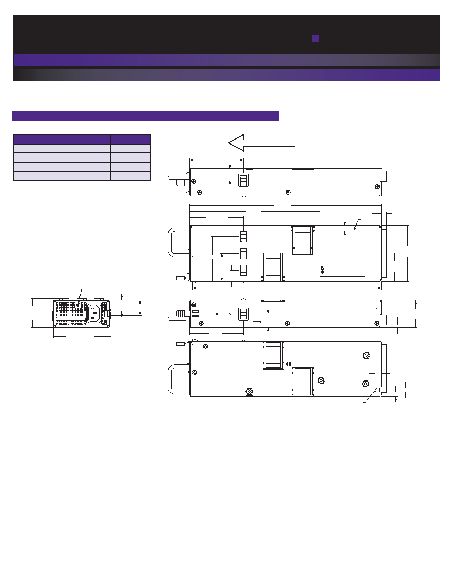
.315"
(8.0)
7.48"
(190.0)
3.09"
(78.5)
.767"
(19.5)
(3X) 3.09"
(78.5)
(15.5)
(40.5)
(65.5)
3.09"
(78.5)
.649
(16.5)
1.58"
(40.2)
CLIP COMPRESSED
AIRFLOW DIRECTION
BI-COLOR LED
11.0" ± .02"
(279.4 ±0.5)
10.85" ±.03"
(275.5 ±0.7)
.354"
(9.0)
.256"
(6.5)
.236"
(6.0)
1.57" ±.02"
(39.9 ±0.5)
.142" ±.02"
(3.6 ±0.5)
3.20" ±.02"
(81.3) ±0.5
1.60"
(40.7)
.275"
(7.0)
(2X) 3.30" ±.03"
(83.8 ±0.7)
.897" ±.02
(22.8 ± 0.6)
.638" ±.02"
(16.2 ±0.6)
SEE NOTE 3
FULL R
MODEL DS850-3
ASTEC
Condition
LED Status
+3V3SB-ON; +12VOUT-OFF; A
AC
C P
PR
RE
ES
SE
EN
NT
T
Blinking Green
+3V3SB-ON, +12VOUT-ON
Solid Green
+
+1
12
2V
V_
_O
OC
CP
P,, +
+1
12
2V
V_
_U
UV
VP
P,, +
+1
12
2O
OV
VP
P
Blinking Red
F
FA
AN
N_
_FFA
AU
ULLT
T,, O
OT
TP
P,, 3
3V
V3
3 O
OC
CP
P//U
UV
VP
P
Solid Red
Mechanical Drawing
Rev. 03.13.06
DS850-3
4 of 4
Emerson Network Power and the Emerson
Network Power logo are trademarks and
service marks of Emerson Electric Co.
©2006 Emerson Electric Co.
Embedded Power for
Business-Critical Continuity
Emerson Network Power.
The global leader in enabling
business-critical continuity.
EmersonNetworkPower. com
AC Power
Connectivity
DC Power
Embedded Power
Inbound Power
Integrated Cabinet Solutions
Outside Plant
Precision Cooling
Site Monitoring and Services
Astec Power
5810 Van Allen Way
Carlsbad, CA 92008
USA
Telephone: +1 760 930 4600
Facsimile: +1 760 930 0698
Technical Support: +1 888 41 ASTEC
or +1 407 241 2752
Waterfront Business Park
Merry Hill, Dudley
West Midlands, DY5 1LX
United Kingdom
Telephone: +44 (0) 1384 842 211
Facsimile: +44 (0) 1384 843 355
Units 2111-2116, Level 21
Tower 1, Metroplaza
223, Hing Fong Road
Kwai Fong, New Territories
Hong Kong
Telephone: +852 2437 9662
Facsimile: +852 2402 4426
For global contact, visit:
www.astecpower.com
technicalsupport@astec.com
While every precaution has been taken to ensure
accuracy and completeness in this literature, Astec
Power assumes no responsibility, and disclaims
all liability for damages resulting from use of this
information or for any errors or omissions.
Printed in US A
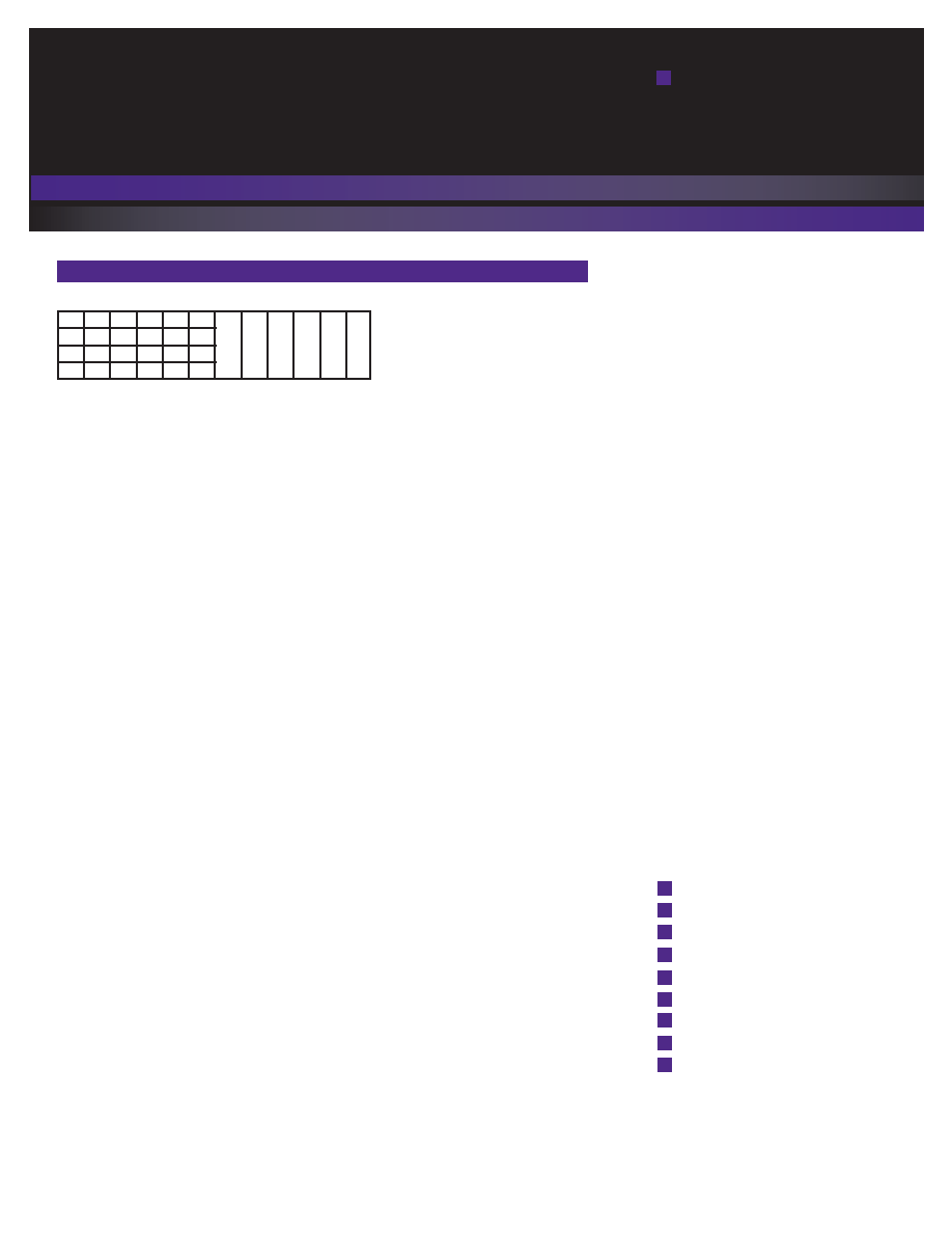
DC Output Connector Pinout Assignment
P
Piin
n
S
Siig
gn
na
all N
Na
am
me
e
PB 1
+12V RETURN
PB 2
+12V RETURN
PB 3
+12V RETURN
PB 4
+12V
PB 5
+12V
PB 6
+12V
A1
PS_ON
A2
+12V RMT SENSE RETURN
A3
TEMP_OK
A4
PS_SEATED ( Power Supply Seated)
A5
+3V3 STAND-BY
A6
+3V3SB RETURN
B1
AC_OK (AC Input Present)
B2
+12V RMT SENSE
B3
+12V CURRENT SHARE
B4
PS_INHIBIT
B5
+3V3 STAND-BY
B6
+3V3SB RETURN
C1
SDA (I2C Data Signal)
C2
SCL (I2C Clock Signal)
C3
POWER GOOD
C4
FAN FAIL (Fan Fail Signal)
C5
+3V3 STAND-BY
C6
+3V3SB RETURN
D1
A0 (I2C Address BIT 0 Signal)
D2
A1 (I2C Address BIT 1 Signal)
D3
S_INT (Alarm)
D4
+3V3 STAND-BY RMT SENSE
D5
+3V3 STAND-BY
D6
+3V3SB RETURN
P
P1
1 -- P
Po
ow
we
err S
Su
up
pp
pllyy S
Siid
de
e
1. FCI Power Blade 51721 series
51721-10002406AA
2. Molex Power Connector
SD-87667 series
87667-7002
M
Ma
attiin
ng
g C
Co
on
nn
ne
ecctto
orr ((S
Syysstte
em
m ssiid
de
e))
1.FCI Power Blade
51741-10002406CC
Strait Pins
2.FCI Power Blade
51761-10002406AA
Right Angle
D1
D2
D3
D4
D5
D6
PB1 PB2 PB3 PB4 PB5 PB6
C1
C2
C3
C4
C5
C6
B1
B2
B3
B4
B5
B6
A1
A2
A3
A4
A5
A6
Male connector as viewed from the rear of the supply: