
rev 02.24.05
Technical Support: (888) 41-ASTEC or (407) 241-2752
Americas: (760) 930-4600 Europe (UK) 44 (1384) 842-211
Asia (HK) 852-2437-96622
Special Features
Electrical Specs
350-1400 Watts
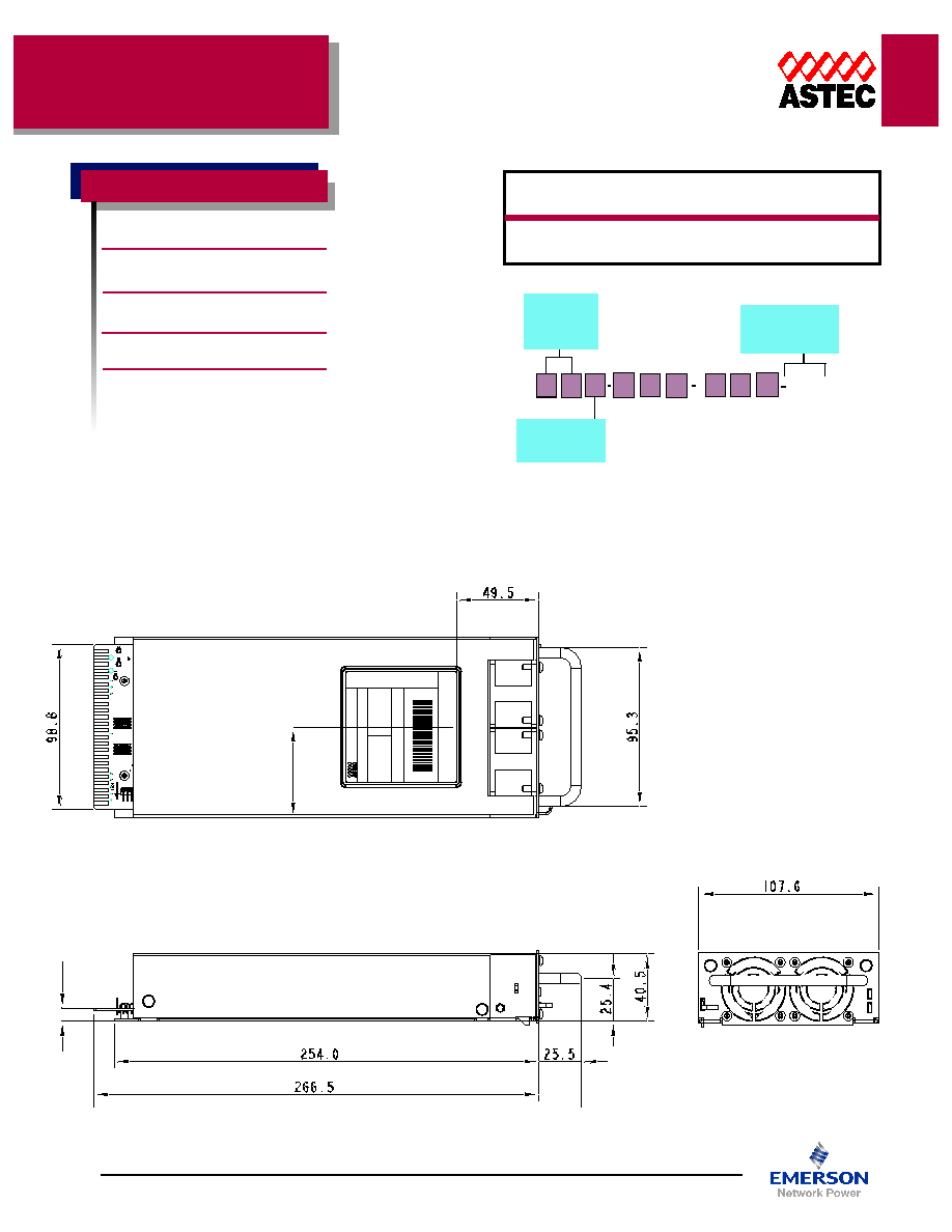
HPS35 Series
∑ Active Power Factor Correction
∑ EN61000-3-2 compliant
∑ CISPR22, EN55022 Class-B conducted/radiated EMI
∑ EN61000 immunity standards
∑ 5VSB@2A
∑ Overvoltage protection (OVP)
∑ Overcurrent protection (OCP)
∑ Overtemperature protection (OTP)
∑ AC OK signal and indicator LED
∑ DC OK signal and indicator LED
∑ Remote inhibit
∑ Remote Sense on main output
∑ Hot Plug
∑ N+1 Redundant
∑ Optional I
2
C board (pending)
Voltage Monitoring
Current Monitoring
Remote on/off
DC OK / AC OK
Temperature
Fan fail
Input
Input voltage
90-264 VAC typical
Frequency
47-440 Hz
Inrush current
40 A peak typical @ 25∞C
Efficiency
80% typ @ full load, 230 VAC
Power factor
0.98 typical @ 115 VAC, full load
Turn-on time
AC - ON 2 sec.
Inhibit / Enable 160 ms
EMI filter standard
CISPR 22 EN55022 Level "B"
Leakage current standard <0.5 mA max @ 230 VAC @ 60Hz
(per module)
Radiated EMI
CISPR 22 EN55022 Level "B"
Holdup time
20 ms minimum
(independent of input VAC)
AC OK
5 ms early warning minimum before
outputs lose regulation
Harmonic distortion
Meets EN61000-3-2
Isolation
Meets EN60950
Output
Adjustability
±5% of nominal output voltage
Overall reg
<3%
Ripple
1% of Vout Pk - Pk
(20 MHz bandwidth)
Dynamic response
4% with 50% load step
Recovery time
To within 1% in <300 µsec
Overcurrent protection
115%-130% of rated output current
Short circuit protection
Protected for continuous short circuit.
Auto recovery.
Overvoltage protection
120 - 140% . AC Reset.
Reverse voltage protection 100% of rated output current
Thermal protection
Main and Aux disabled when internal
temp exceeds safe operating range.
Remote sense
Up to 0.5 V total drop
Single wire parallel
Current share to within 10% of total
rated current on main output
DC OK
±5% of nominal
Minimum load*
None required (as a standalone module)
Standby voltage
5 VDC @2A max. present whenever AC
input is applied
Global Inhibit
Logic "0"
*3A minimum required for current share operation
Environmental
Total ppower:
350W
Input vvoltage: 90-2264VAC
# oof ooutputs: One &
& sstandby
UL
UL60950-1, 1st Ed. (April 1, 2003)
CSA
CSA C22.2 60950-1-03
TUV
EN60950-1:2001 (1st Ed.)
CB
IEC60950-1, 1st Ed. (2001)
CE
Mark (LVD)
Operating temperature: 0∞C to +50∞C ambient, derate
output @ 2.5% per degree from 50∞C to 70∞C
Shock: Operating - 4g, half since, 22 ms minimum
duration, all 6 faces
Non-operating: 30g, half since, 6 ms minimum
duration, all 6 faces
Random Vibration
Operating: 1g rms, 20 min/axis
Non-operating: 12.5g rms, 20min/axis
Humidity: 95% non-condensing
Storage temperature: -40∞C to +85∞C
Temperature coefficient: 0.04% per ∞C
Cooling: Internal DC fans
Safety
ASIA
Units 2111-2116, Level 21
Tower1, Metroplaza
223, Hing Fong Road
Fwai Fong, New Territories
Hong Kong
Telephone: 852-2437-9662
Facsimile: 852-2402-4426
E
EU
URRO
OPPEE
Astec House, Waterfront Business Park
Merry Hill, Dudley
West Midlands, DY5 1LX, UK
Telephone: 44 (1384) 842-211
Facsimile: 44 (1384) 843-355
A
AM
MEERRIIC
CA
ASS
5810 Van Allen Way
Carlsbad, CA 92008
Telephone: 760-930-4600
Facsimile: 760-930-0698
www.astecpower.com
Watts
350
Input
Voltage
90-264
Module ID
HPS35
Code
Volts
Output Amps
L
12.0
29.2
W
48.0
7.3
Module
Max. Size
Max. Module
Number
Unit
Code
(H x W x L)
Power
per Rack Weight (lbs)
HPS35
1.6" x 4.3" x 10.5"
350 W
4
3.2
Modules
Output Voltage
L = 12 V
W = 48 V
Power
35 = 350 W
50 = 500 W
HPS
XXX
Special Options
& Modifications
Contact Astec
N
N
0 0 0
N R
H
HPPSS3355LL-N
NN
NRR-000000
7.6
53.8
HPS35L-NNR-000
MAXIMUM OUTPUT POWER IS 350W
DATE: YYWW
S/N: MMMMWWSSSSRRC
MADE IN PHILIPPINES
INPUT:
90 - 240VAC - 40A
50/60 Hz
SERIAL NO.:
OUTPUT:
+12V / 29A
REV: XX
A/C CODE: XXXX
73-811-029
HPS35

North America (USA): 1-888-41-ASTEC
Europe (UK): 44 (1384) 842-211
Asia (HK): 852-2437-9662
154
Pin Assignments
rev 02.24.05
H
HPPSS3355 M
Moodduullee
1
A
B
C
D
E
F
H
J
K
L
M N
P
R
S
T
U
V
W X
Y
Z
AA AB
2
3
4
5
6
7
8
9
10
11
12
13
14
15
16
17
18
19
20
21
22
23
24
TOP SIDE 1-24
Mating cconnector:
EDAC 307-048-520-201 or
equivalent
Rating: 5A per contact
Unit C
Connector
Card Edge Connector with gold fingers double-sided 1.6mm FR-4 PCB
P
Piinn 66 - SSW
WPP (IN/OUT Signal)
(
(SSiinnggllee W
Wiirree PPaarraalllleell))
SWP Pin is used when
connecting units in parallel
to achieve current sharing.
Current share accuracy is
typically 10% of full load.
Note:
SWP Voltage is 5V at 100% load current
P
Piinn 2233 - FFaann M
Moonniittoorr (OUT Signal)
P
Piinn ZZ - A
AC
C O
OKK (OUT Signal)
P
Piinn FF - --RReem
moottee SSeennssee
P
Piinn H
H - ++ RReem
moottee SSeennssee
Compensates for up to 0.5V drop.
Recommended shielded twisted wire
pair.
P
Piinn X
X - M
Moodduullee IInnhhiibbiitt (IN Signal)
Note:
SWP Voltage is 5V at 100% load current
Note:
Hi state: Source 100uA @ 4V
Low State: Sink 10mA @ 0.5V
P
Piinn A
AA
A - D
DC
C O
OKK (OUT Signal)
Unit C
Connector
Card Edge Connector with gold fingers double-sided 1.6mm FR-4 PCB
Pin Description
1
AC (L)
2
BLANK
3
AC (N)
4
BLANK
5
GND
6
SWP
7
5V RTN
8
COMMON
9
COMMON
10 COMMON
11 COMMON
12 COMMON
13 COMMON
14 V OUT
15 V OUT
16 V OUT
17 V OUT
18 V OUT
19 V OUT
20 BLANK
21 +5 STANDBY
22 TBA
23 FAN MON
24 I
2
C CLK
Pin Description
A
AC (L)
B
BLANK
C
AC (N)
D BLANK
E
GND
F
-SENSE
H +SENSE
J
COMMON
K
COMMON
L
COMMON
M COMMON
N COMMON
P
COMMON
R
V OUT
S
V OUT
T
V OUT
U
V OUT
V
V OUT
W V OUT
X
INHIBIT
Y
TBA
Z
AC OK
AA DC OK
BB I
2
C DATA
Bottom
Top

E
EU
URRO
OPPEE
Astec House, Waterfront Business Park
Merry Hill, Dudley
West Midlands, DY5 1LX, UK
Telephone: 44 (1384) 842-211
Facsimile: 44 (1384) 843-355
A
AM
MEERRIIC
CA
ASS
5810 Van Allen Way
Carlsbad, CA 92008
Telephone: 760-930-4600
Facsimile: 760-930-0698
155
www.astecpower.com
ASIA
Units 2111-2116, Level 21
Tower1, Metroplaza
223, Hing Fong Road
Fwai Fong, New Territories
Hong Kong
Telephone: 852-2437-9662
Facsimile: 852-2402-4426
330.2
343.2
13.4
468.8
442.0
31.7
43.7
482.6
25.0
22.0
DATE: YYWW
S/N: MMMMWWSSSSRRC
MADE IN PHILIPPINES
REV: XX
A/C CODE: XXXX
73-810-002
SERIAL NO.:
MAXIMUM OUTPUT POWER IS 1400W
INPUT:
90 - 240VAC - 40A
50/60 Hz
OUTPUT:
+12V / 29A
HPR1-00
+
RTN
+
RTN
AC C
Cord: (North America)
For all other countries, please contact factory.
1) Quail Electronics Series 5050 or equivalent
(15A/125V)
Supply End - NEMA 5-15P
Equipment End - IEC 60320-C19
2) Quail Electronics Series 5052 or equivalent
(20A/125V)
Supply ENd - NEMA 5-20P
Equipment End - IEC60320-C19
Blank PPanel:
Astec P/N 73-686-000
HPS35 Series
DRAWINGS
H
HPPRR11 -0000
System
Max. Size
Max. System
Module
Standard
Unit
Code
(H x W x L)
Power
Distribution
Size
Weight (lbs.)
HPR1
1.75" x 19.0" x 13.0"
1400 W
(4 ea) HPS35
1U
8.6
Racks
Watts
1400 (fully populated)
Input
Voltage
90-264
Module Used
HPS35
Rack ID
HPR1
Code
Volts
Output Amps
L
12.0
116.8
W
48.0
29.2
HPR1 -
Standard Options
00 = No options
01 = Local sense

P
Piinn 22 ++ RReem
moottee SSeennssee
P
Piinn 33 - RReem
moottee SSeennssee
Compensates for up to 0.5V drop.
Recommended shielded twisted wire
pair.
P
Piinn 1122 - G
Glloobbaall A
AC
C O
OKK (OUT signal)
Note: AC OK signals are OR'ed together
internally. If any module fails, the LED
on the affected module will be off and
the logic signal will indicate AC NOT OK.
P
Piinn 1199 - G
Glloobbaall IInnhhiibbiitt (IN signal)
Note: All outputs disabled when Pin 19
is open or High.
P
Piinn 2222 - SSW
WPP (IN/OUT signal)
SWP Pin is used when
connecting racks in
parallel to achieve
current sharing. Current
share accuracy is
typically 10% of full load.
Note: SWP Voltage is 5V at 100% load
current.
M
Moodduullee IInnhhiibbiitt (IN Signal)
Note: Module Inhibit signals for each
slot in the rack is accessible in the D-sub
connector (J18). Refer to Connector Pin-
out table for pin assignments. Pin 1 is
the Return Pin.
North America (USA): 1-888-41-ASTEC
Europe (UK): 44 (1384) 842-211
Asia (HK): 852-2437-9662
156
rev 02.24.05
H
HPPRR11 -0000
D-sub Connector Pin outs
Pin Description
1
5V Return (std-by)
2
+ Remote Sense
3
- Remote Sense
4
5V Stand by
5
Unused
6
Module Inhibit
7
DC OK
8
AC OK
9
I2C_ADD#1
10 I2C_ADD#2
11 Fan Monitor
12 Global AC OK
13 Module Inhibit
14 DC OK
15 AC OK
16 I2C_ADD#1
17 I2C_ADD#2
18 Fan Monitor
19 Global Inhibit
D
DC
C O
OKK (OUT Signal)
Note: DC OK signals for each slot in the
rack is accessible in the D-sub
connector (J18). Refer to Connector
Pin-out table for pin assignments. Pin 1
is the Return Pin.
A
AC
C O
OKK (OUT Signal)
Note: AC OK signals for each slot in the
rack is accessible in the D-sub
connector (J18). Refer to Connector
Pin-out table for pin assignments. Pin 1
is the Return Pin.
Hi state: Source 100uA @ 4V
Low State: Sink 10mA @ 0.5V
F
Faann M
Moonniittoorr (OUT Signal)
Note: Fan Monitor signals for each slot
in the rack is accessible in the D-sub
connector (J18). Refer to Connector
Pin-out table for pin assignments. Pin 1
is the Return Pin.
I2C_ADD#1
I2C_ADD#2
TBD
PSU C
Connector
617-A-037-P-AJ-1-21 (Male socket) Amphenol
Pin Out Diagram D-sub Connector (male)
Mating C
Connector
617-A-037-S-AJ-1-20 (Female socket) Amphenol
Pin Out Diagram D-sub Connector (female)
S
L
O
T
1
Pin Description
20 I2C CLOCK
21 I2C DATA
22 SWP
23 Unused (I2C_INT)
24 Module Inhibit
25 DC OK
26 AC OK
27 I2C_ADD#1
28 I2C_ADD#2
29 Fan Monitor
30 Unused
31 Module Inhibit
32 DC OK
33 AC OK
34 I2C_ADD#1
35 I2C_ADD#2
36 Fan Monitor
37 Unused
S
L
O
T
2
S
L
O
T
3
S
L
O
T
4