Embedded Power for
Business-Critical Continuity
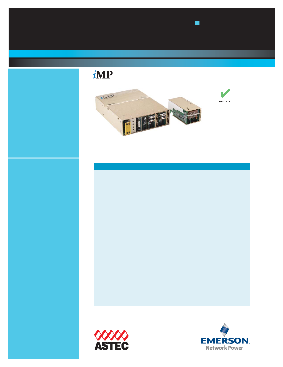
Intelligent MP
Series
Up to 1500 Watts
Special Features
∑ Full Medical EN60601 Approval
∑ Intelligent I
2
C Control
∑ Configurable Current Share
on all outputs >10A
∑ Voltage adjustment on all out-
puts (Manual or I
2
C)
∑ Configurable Input and Output
OK signals and indicators
∑ Configurable Inhibit/Enable
∑ Configurable Output
UP/DOWN sequencing
∑ Intelligent fan
(speed control/fault status)
∑ Customer Provided Air Option
∑ uP Controlled PFC input with
active Inrush protection
∑ I
2
C monitor of Voltage,
Current, and Temp
∑ IPMI Compliant
∑ Programmable Voltage, Current
Limit, Inhibit/Enable through I
2
C
∑ Optional Extended Hold-up
Module
(Semi F47 compliance)
∑ Power density increased by 50%
∑ Backward compatibility with
standard MP
∑ External switching frequency
sync input
∑ Optional Conformal Coating
∑ Industrial Temp Range
∑ No preload required
Total Power:
Up to 1500 Watts
Input Voltage: 85 - 264 VAC
120-300 VDC
# of Outputs: Up to 21
Electrical Specifications
TM
RoHS
Rev. 1.30.06
iMP Series
1 of 8
Input
Input range
85-264 VAC: 120-350 VDC
(Limited to 300VDC in medical applications)
Frequency
47-440 Hz
Inrush current
40A peak max. (soft start)
Efficiency
up to 85% @ full case load
Power Factor
0.99 typ. meets EN61000-3-2
Turn-on time
AC on 1.5 sec typ., Inhibit / Enable 150 ms typ.
Programmable
EMI Filter
CISPR 22 / EN55022 Level "B"
Leakage current
300 A max. @ 240 VAC; 47-63Hz
Radiated EMI
CISPR 22 / EN55022 Level "B"
Holdover storage
20 ms minimum (independent of input VAC) additional
34mSEC holdover storage with optional HUP module
(Semi F47 compatible)
AC OK
>5 ms early warning min. before outputs lose regulation.
Programmable. Full cycle ride thru (50 Hz)
Harmonic distortion
Meets EN61000-3-2
Isolation
Meets EN60950 and EN60601
Global Inhibit/Enable
TTL, Logic "1" and Logic "0". Configurable.
Input fuse (internal)
iMP4: 10A; iMP8: 20A; iMP1: 20A (both lines fused)
Warranty
2 years

Rev. 1.30.06
iMP Series
2 of 8
Output
Adjustment range*
±10% minimum all outputs (manual)
(full module adjustment range using II
2
2
C
C)
Margining
±4-6% nominal analog (single output module only)
Overall reg
0.4% or 20 mV max. (36W modules 4% max.)
Ripple
RMS: 0.1% or 10 mV, whichever is greater
Pk-Pk: 1.0% or 50 mV, whichever is greater
Bandwidth limited to 20 MHz
Dynamic response
<2% or 100 mV, with 25% load step
Recovery time
To within 1% in <300 sec.
Overcurrent protection* Configurable through II
2
2
C
C. Single output module and main out-
put of the dual output module 105-120% of rated output cur-
rent. Aux output of dual output module 105-140% of rated
output current
Triple output module internally protected
Short circuit protection
Protected for continuous short circuit
Recovery is automatic upon removal of short
Overvoltage protection* Configurable through I
2
C
Single output module
2-5.5V 122-134% ; 6-60V 110-120%
Dual output module
2-6V 122-134% ; 8-28V 110-120%
Triple output module
No overvoltage protection provided
Reverse voltage protection 100% of rated output current
Thermal protection*
Configurable through II
2
2
C
C
All outputs disabled when internal temp exceeds safe operat-
ing range. >5 ms warning (AC OK signal) before shutdown
Remote sense
Up to 0.5 V total drop (not available on triple output module)
Singlewire parallel
Configurable through firmware
Current share to within 2% of total rated current
D
DC
C O
OK
K*
*
+/-5% of nominal. Configurable through II
2
2
C
C
Minimum load
Not required
Housekeeping bias voltage 5 VDC @1.0Amp max. present whenever AC input is applied
Module inhibit*
Configured and controlled through II
2
2
C
C
Switching frequency
250 kHz accepts external sync signal
Output/Output isolation
>1 Megohm, 500V
VME signal*
DC OK signal programmable through II
2
2
C
C to function
as POR signal
*Can be controlled via I
2
C
Safety
UL
UL60950/UL2601
CSA
CSA22.2 No. 234 Level 5
VDE
EN60950/EN60601
BABT Compliance to
EN 60950/EN60601 BS 7002
CB
Certificate and report
CE
Mark to LVD
Module Code
1
1
2
2
3
3
4
4
N
No
on
ne
e
Module Type
S
Siin
ng
glle
e
S
Siin
ng
glle
e
S
Siin
ng
glle
e
D
Du
ua
all
T
Trriip
plle
e
Max output power
210W
360W
750W
144W
36W
Max output current
35A
60A
150A
10A
2A
Output voltages available*
2-60V
2-60V
2-60V
5, 12-15, 28-30V 2-6, 12-15, 28-30V 8-15V 8-28V 2-28V
Standard voltage increments
25
25
25
19
18
Remote sense
Yes
Yes
Yes
Yes
Yes
No
No
No
Remote margin
Yes
Yes
Yes
No
No
No
No
No
V-Program - I
2
C Control
Yes
Yes
Yes
Yes
Yes
Yes
Yes
Yes
Active Current Share
Yes
Yes
Yes
Yes
No
No
No
No
Module Inhibit - I
2
C Control
Yes
Yes
Yes
Yes
Yes
Yes
Yes
Yes
Module Inhibit - Analog
Yes
Yes
Yes
No
No
No
No
No
Over voltage / Over current protection
Yes
Yes
Yes
Yes
Yes
Yes
Yes
Yes
Minimum load required
No
No
No
No
No
No
No
No
Slots occupied in any iMP case
1
2
3
1
1
Output Module Line-up
*Programmable
Operating
temperature
-40∞ to 70∞C ambient. Derate
each output 2.5% per degree
from 50∞ to 70∞C.
( -20∞C start up)
Storage
temperature
-40∞C to +85∞C
Electromagnetic
susceptibility
Designed to meet EN61000-
4; -2, -3, -4, -5, -6, -8, -11
Level 3
Humidity
Operating; non-condensing
10% to 95% RH
Vibration
IEC68-2-6 to the levels of
IEC721-3-2
MTBF
demonstrated
>550,000 hours at full load,
220VAC and 25∞C ambient
conditions
Environmental
Specifications

Embedded Power for
Business-Critical Continuity
Rev. 1.30.06
iMP Series
3 of 8
Voltage
Voltage
Code
Single Output Module Code
Dual Output
Triple Output
I
I
2
2
C
C
Adjustment
Ranges
1
2
3
V1
V2
V1
V2
V3
2V
A
35A
60A
150A
--
10A
--
--
2A
1.8 - 6.1
2.2V
B
35A
60A
150A
--
10A
--
--
2A
3V
C
35A
60A
150A
--
10A
--
--
2A
3.3V
D
35A
60A
150A
--
10A
--
--
2A
5V
E
35A
60A
150A
10A
10A
--
--
2A
5.2V
F
35A
60A
150A
--
10A
--
--
2A
5.5V
G
34A
58A
137A
--
10A
--
--
2A
6.0V
H
23A
42A
80A
--
10A
--
--
2A
5.4 - 13.2
8.0V
I
20A
36A
80A
--
--
1A
1A
1A
10V
J
18A
32A
75A
--
--
1A
1A
1A
11V
K
17A
31A
68A
--
--
1A
1A
1A
12V
L
17A
30A
62.5A
10A
4A
1A
1A
1A
14V
M
14A
21A
53.5A
9A
4A
1A
1A
1A
12.6 - 22.0
15V
N
14A
20A
50A
8A
4A
1A
1A
1A
18V
O
11A
19A
41.6A
--
--
--
0.5A
0.5A
20V
P
10.5A
18A
37.5A
--
--
--
0.5A
0.5A
24V
Q
8.5A
15A
31.3A
4A
2A
--
0.5A
0.5A
21.6 - 39.6
28V
R
6.7A
12.8A
26.8A
3A
2A
--
0.5A
0.5A
30V
S
6.5A
12A
25A
--
--
--
33V
T
6.2A
11A
22.7A
--
--
--
--
--
36V
U
5.8A
10A
20.8A
--
--
--
--
--
42V
V
4.2A
7.5A
17.9A
--
--
--
--
--
37.8 - 60.0
48V
W
4.0A
7.5A
15.6A
--
--
--
--
--
54V
X
3.7A
6.0A
13.9A
--
--
--
--
--
60V
Y
3.5A
6.0A
12.5A
--
--
--
--
--
Non-std*
Z
Special Voltage - Consult Factory for specifications
*Note: Increments of current not shown can be achieved by paralleling modules
(add currents of each module selected).
7
6
5 4
3
2
1
i
MP4
available slots
i
MP8
available slots
Slot 1
Slot 2
Slot 3
Slot 4
Slot 5
Slot 1
Slot 2
Slot 3
Slot 4
Slot 5
Slot 6
Slot 1
Slot 2
Slot 3
Slot 4
Slot 6
Slot 7
Slot 5
i
MP1
available slots
PARALLEL CODES
0 = no parallel
1 = 1 & 2
2 = 2 & 3
3 = 3 & 4
4 = 4 & 5
5 = 3 & 4 & 5
6 = 5 & 6
7 = 4 & 5 & 6
8 = 6 & 7
9 = 3 & 4, 6 & 7
Ordering Information
Output Module Voltage/Current
iMP1*
- 3L0 - 2E2 - 1Q1 - 4LL0 -
00
-
A
-
###
Case Size (mm)
4 = 2.5" x 5" x 10"; 750W - 1100W, 5 Slots
(63.5 x 127 x 254)
8 = 2.5" x 7" x 10"; 1000W - 1200W, 6 Slots
(63.5 x 177.8 x 254)
1 = 2.5" x 8" x 11"; 1200W - 1500W, 7 Slots
(63.5 x 203.2 x 279.4)
*Note: Add "-E" after iMP4 to denote IEC
input option. eg. iMP4-E-...
(Not available on iMP8 or iMP1.)
Module Codes
Module/Voltage/Option Codes
Module Codes:
(None) = 36W Triple O/P (1 slot)
1 = 210W Single O/P (1 slot)
2 = 360W Single O/P (2 slot)
3 = 750W Single O/P (3 slot)
4 = 144W Dual O/P (1 slot)
5 - 9 = Future
Case Option Codes
First Digit
0 - 9 = Parallel Code
Second Digit
0 = No Options
1 = Reverse Air
2 = Extended Hold Up (1 slot)*
3 = Global Enable
4 = Fan Off w/Inhibit
5 = Opt 1 + Opt 3
6 = Opt 1 + Opt 4
7 = Opt 3 + Opt 4
8 = Opt 1 +3 +4
9 = Future
*Meets Semi F47
Software Code
Hardware Code
Voltage Codes:
See Output Module Voltage/Current
table above
Option Codes:
0 = Standard
1 = Module Enable
2 = Constant Current
3 - 9 = Future
Module/Voltage/Option Codes
First - Module Code
Second - Voltage Code
Third - Option Code
Case Option Codes
Factory Assigned for Modified Standards
Standard is "A" - Software Code
"Blank" - Hardware Code
Case Size
Embedded Power for
Business-Critical Continuity
Rev. 1.30.06
iMP Series
4 of 8
Drawings
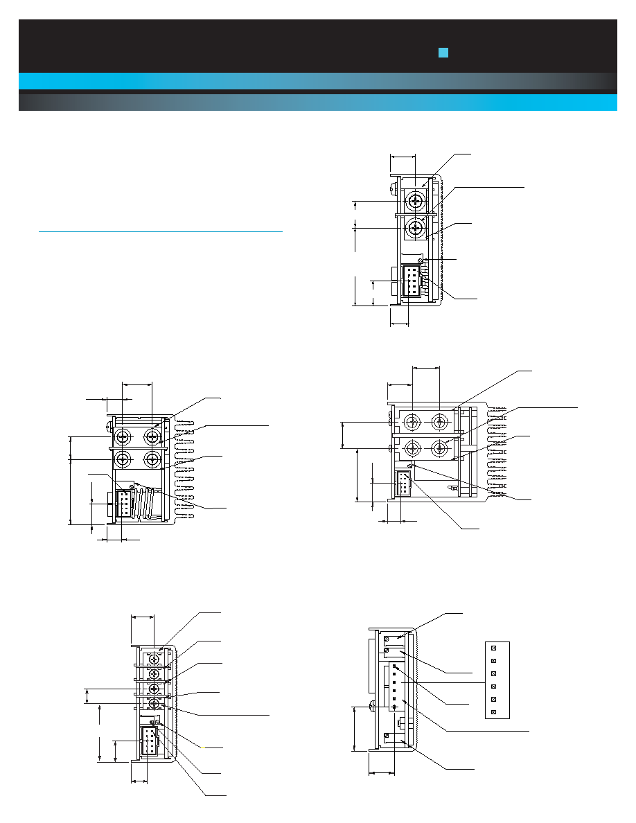
DC-DC Converter Output Modules
Control Signal Information, J1 Control Connector
Pin No.
Function
1
+ Remote Sense
single or dual o/p main
2
Remote Margin / V. Program
single o/p
3
Margin High
single o/p
4
- Remote Sense / Margin Low
single or dual o/p main
5 Spare
6
Module, Isolated Inhibit
single or dual o/p
7
Module Inhibit return
single or dual o/p
8
Current Share (SWP)
single or dual o/p main
9
+ Remote Sense V2
dual o/p, single is spare
10
- Remote Sense V2
dual o/p, single is spare
*Note: All iMP modules have a green DCOK LED.
V2 ADJ
V1 ADJ
PIN 1
V3 ADJ
DC OUTPUT CONNECTION
.48
(12.1)
V1
+
V1
-
V2
+
V2
-
V3
+
V3
-
.84
(21.3)
PIN 1
V+
M4X8 SCREWS (4X)
V-
V ADJ
.32 (8.1)
.44 (11.3)
(2X)
(2X)
.33 (8.5)
.63 (16.0)
.48 (12.1)
1.38 (35.1)
M4X8 SCREWS (4X)
V-
PIN 1
V ADJ
V+
.44
(11.3)
.32
(8.1)
1.24 (31.6) (2X)
.61 (15.6)
(2X)
.63
(16.0)
.59
(15.0)
PIN 1
.32
(8.1)
.44 (11.2 )
(2X)
V+
M4X8 SCREWS (2X)
V-
V ADJ
.48 (12.1)
.44 (11.3)
1.38
(35.1)
PIN 1
V1 ADJ
.32
(8.1)
.42 (10.7)
V1 +
V1 -
V2 -
V2 +
M3X8 SCREWS (4X)
.46 (11.7)
(4X)
.30 (7.5)(3X)
V2 ADJ
1.17 (29.7)
Single 210 Watt
Dual 144 Watt
Triple 36 Watt
Single 360 Watt
Single 250 Watt
i
MP Modules
Embedded Power for
Business-Critical Continuity
Rev. 1.30.06
iMP Series
5 of 8
Notes
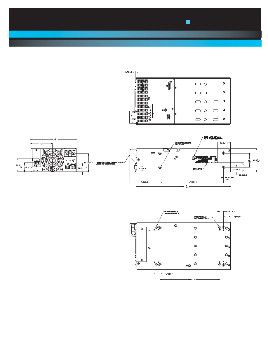
1. Input: Barrier type. Three No. 6-32 B.H. screws (0.375" centers). Max torque: 6 in-lbs. (0.67 N-m).
2. Control connectors: (J1) 10 position housing, gold plated contacts. Mates with Molex 90142-0010 housing with 90119-2110 crimp contacts (Molex C -
Grid III Series) or AMP Model number 87977-3 with 87309-8 pins. Connector kit includes mating connector and 10 pins,
Astec part #70-841-004. J2 10 position housing (Landwin 2051P1000T). Mates with housing 205051000 (Landwin) with 2053T011P (Landwin) pins.
3. Chassis material: aluminum with chemical film coating (conductive).
4. All dimensions are in millimeters and inches, and are typical.
5. Customer mounting -3 sides M4, bottom also includes 8-32 mounting holes. Max. penetration is 0.150" (3.8mm). Max. torque: 5in-lbs.
6. Output module connections: All single O/P modules are M4 x 8mm screws. Max. torque: 10in-lbs.
Dual O/P module is M3 x 8mm screws. Max. torque: 5 in-lbs.
Triple O/P module is .045" square pins on .156" centers. Mates with Molex 09-50-8063 or equivalent.
i
MP Series
i
MP4 (750/1100 Watts Max)
5
5--IIn
ncch
h C
Ca
asse
e S
Siizze
e:: iMP4: 2.5" x 5" x 10" (63.5mm x 127mm x 254mm)
W
We
eiig
gh
htt:: iMP4 Case: 2.6 lbs. ∑ 36 W Triple: 0.5 lb. 210 W Single: 0.6 lb.
∑ 360 W Single 1.0 lb. ∑ 600 W Single: 2.0 lbs. 144 W Dual: 0.6 lb.
Horizontal both sides