1
Main Features
Ј
High Sensitivity Full Frame CCD Sensor
Ј
2300 x 3500 Resolution with 10 µm Square Pixels
Ј
Bayer Color Mosaic
Ј
12-bit Dynamic Range
Ј
Very Low Noise: 63 dB SNR
Ј
Binning and ROI Modes
Ј
LVDS Data Format
Ј
High Data Rate: 25 Mpixels/s
Ј
Flexible and Easy to Operate via RS232 Control
≠ Trigger Mode: Free Run or External Trigger Modes
≠ Binning 2x2 and 4x4, Up to 5 ROI
≠ Exposure Time
≠ Gain: x1 or x4
Ј
Single Power Supply: DC 24V
Ј
High Reliability ≠ CE Compliant
Ј
F (Nikon) Mount Adapter (Lens Not Supplied)
Product Description
This camera is designed to meet high performance and quality requirements while
providing easiness of use.
Ј
ATMEL manages the whole chain, from the sensor to the camera. The result is a
camera able to work in 12-bit, with a dedicated electronic offering an excellent
signal to noise ratio.
Ј
The programmable settings let the user works at different integration time and
gain. External trigger allows to synchronise the camera on external event while
hardware white balance adjustment avoids subsequent software processing.
Applications
Performance and reliability of this camera make it well suited for the most demanding
applications as film and document scanning, semiconductor and PCB inspection,
DNA analysis, metrology, X-ray imaging, etc...
CAMELIACOL
8M
8 Megapixels
Digital Color
Camera
Rev. 1985B≠IMAGE≠03/03
2
CAMELIA 8M Color Digital Camera
1985B≠IMAGE≠03/03
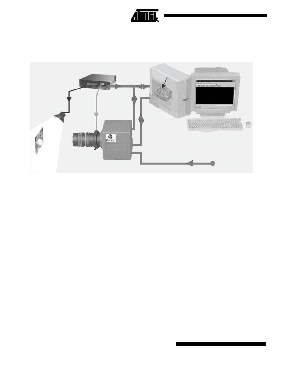
Imaging System
Description
Figure 1. Imaging System
CAMELIA camera is powered by a single +24V power supply.
CAMELIA camera is configurable via the serial port of the computer (by using either
CommCam software or standard RS232 communicator as TTY or Hyperterminal).
CAMELIA camera sends digital video.
As CAMELIA's CCD is a full frame sensor, the user must use either pulsed lightning or a
chopper/shutter in front of the camera in order to have incident lightning on the CCD
only during integration time. The user must design an electro-optical interface to drive
camera, shutter/chopper or lightning by using the "SHUTTER" signal delivered by the
camera. If required, the system can send an external trigger or external ITC (integration
time control signal) to the camera.
The BG38 Filter is essential to have a correct white balance on Color Cameras.
Note that the following Elements are not provided by ATMEL:
Ј
Shutter (LCD or Mechanical)
Ј
BG38 (Anti Infra Red) Filter
Ј
Control Box
Ј
Lens
Ј
Light Source
Ј
+24V Power Supply
Ј
Computer
For a complete explanation of the utility of the BG38 Filter and the Shutter, please con-
sult the associated FAQs and the example Images on the ATMEL CDROM "Camera
Documentation & Software".
Light Source
Light &
Shutter
Trigger
Cables
Lens
Shutter
& BG38
Camera
Power Supply Cable
+24V
RS-232
Cable
Data &
Sync
Cable
Control Box
PC Computer
FGT
Frame Grabber
3
CAMELIA 8M Color Digital Camera
1985B≠IMAGE≠03/03
CCD Description
Image Format
35.0 mm (V) x 23.0 mm (H)
Active Pixels
Readout Register
Readout register along the small side of the image area (vertical image).
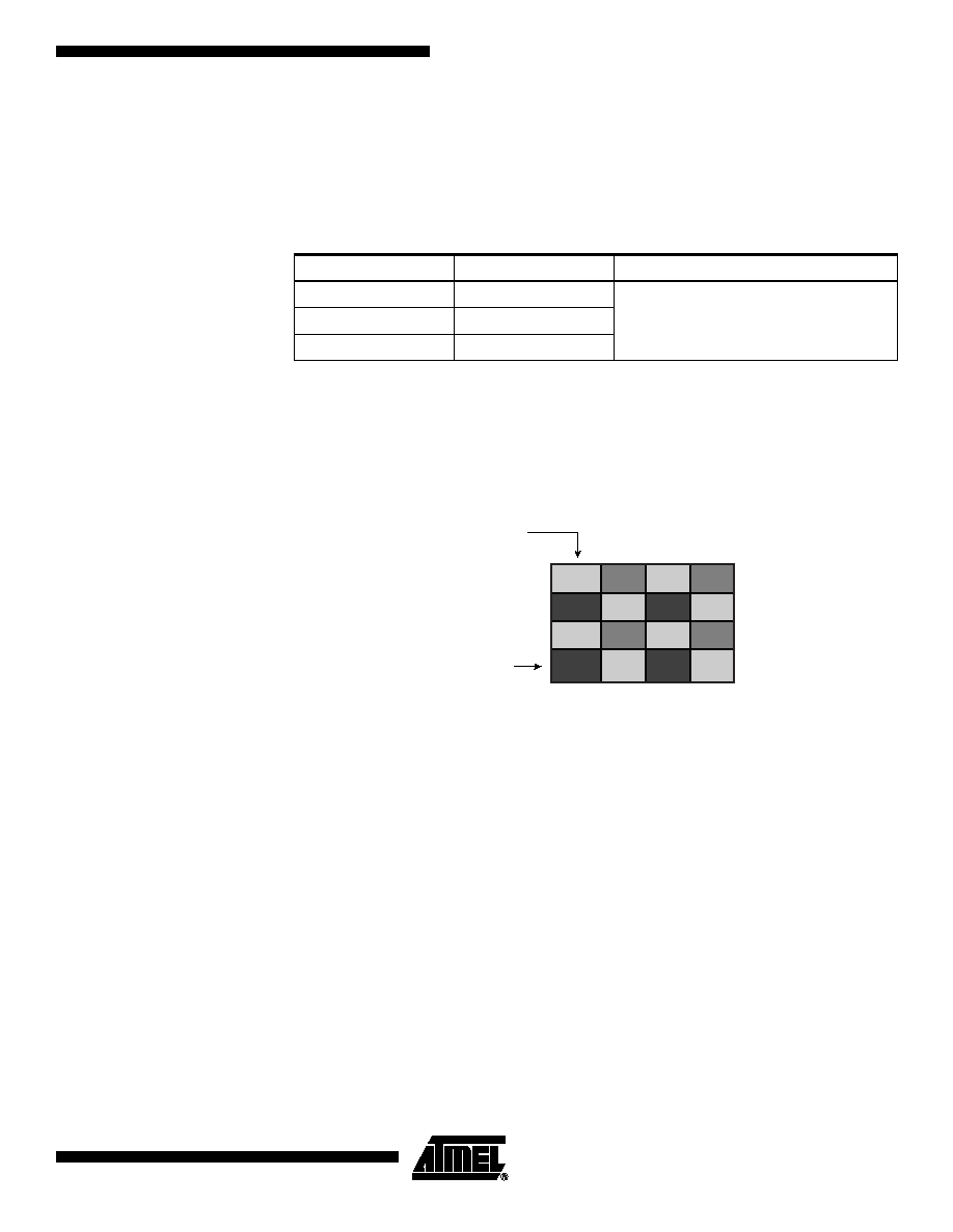
Pixel Geometry
Figure 2. Filter Mosaic (BAYER Pattern)
Note:
First active pixel of first active line is blue.
Anti-blooming by
Clocking
Anti-blooming can be activated or inhibited (see "RS232 Controls" on page 11):
Ј
Anti-blooming OFF: anti-blooming inhibited. This position is recommended if anti-
blooming is not required for the application.
Ј
Anti-blooming ON: anti-blooming activated.
Ј
When binning is disabled, the anti-blooming is efficient until 8 times the saturation
Current.
Table 1. Active Pixels
Mode (set via RS232)
Image size (H x V)
Timing diagram correspondence
No binning
2300 x 3500
H = M
V = N
2x2 pixel binning
1150 x 1750
4x4 pixel binning
574 x 875
First Column
G
R
G
R
B
G
B
G
G
R
G
R
First Line
B
G
B
G

4
CAMELIA 8M Color Digital Camera
1985B≠IMAGE≠03/03
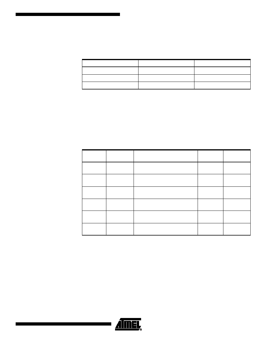
Video Signal Processing
Gain
Video signal processing gain can be adjusted by setting the ''CDS gain'' via RS232: a
commutation 1x or 4x is available at the input of the video signal processing.
The 4x position is recommended for low level applications.
Figure 3. Video Signal Processing Gain
MPP Photosensitive Zone
Output Register
16 Dark References
3500 Lines
2300 Columns
5
CAMELIA 8M Color Digital Camera
1985B≠IMAGE≠03/03
Timing
2x2 and 4x4 pixel binning are possible to enable previewing modes. Preview mode is
only available in Black and white otherwise the user has to use Overlay mode (but nei-
ther correction nor software LUT are applicable on displayed images).
Frame Timing
Three timing modes are available: Continuous, external triggered and Integration Time
controlled (ITC).
The signals described in the following drawings are:
Notes: 1. Pixel is defined as valid (part of the Frame) when both LEN and FEN Signals are at
Low Level.
2. The latency (called Td after) of 1 Readout line Time defined below depends on the
binning mode. For no binning, this precision is around 104 µs.
3. Minimum Time at high level of LEN Signal is 10 µs (Transfer Time between two lines).
4. Minimum Time at high level of FEN Signal is 4 lines readout Time (around 416 µs).
5. Shutter Delay is adjustable via Commcam or RS232 commands (1, 5, 10 or 20 ms).
Table 2. Timing Mode
Mode
Frame Readout Time
Line Readout Time
No binning
370 ms
104 µs
2x2 pixel binning
200 ms
114 µs
4x4 pixel binning
110 ms
134 µs
Table 3. Frame Timing
Signal
Name
Description
Cam.
In/Out
Pins
Connection
LEN
Line ENable
Low state active when pixel is part
of line
Out
26/27
FEN
Frame
ENable
Low state active when lines are
part of frame
Out
3/4
SHUTTER
SHUTTER
Sync
External shutter Trig output Sig.
(high level active)
Out
21/22
TRIG
TRIGger
External Trigger Input Signal
(Rising Edge)
In
46/47
ITC
Integration
Time Control
External ITC Input Signal
(Falling/Rising Edges)
In
46/47
PCK
Pixel Clock
Internal Master Data Clock Signal
at 25 MHz
Out
1/2