
1
Features
∑
Low-power, Low-voltage CMOS IDIC
“
∑
Contactless Power Supply, Data Transmission and Programming of EEPROM
∑
Radio Frequency (RF): 100 kHz to 150 kHz, Typically 125 kHz
∑
Automatic Programmable Adaptation of Resonance Frequency
∑
Easy Synchronization with Special Terminators
∑
High-security Method Unilink Challenge Response Authentication by AUT64 Crypto
Algorithm
∑
Encryption Time < 10 ms, Optional < 30 ms Programmable at 125 kHz
∑
320-bit EEPROM Memory in 10 Blocks of 32 Bits Each
∑
Programmable Read/Write Protection
∑
Extensive Protection Against Contactless Malprogramming of the EEPROM
∑
Programming Time for One Block of the EEPROM Typically 16 ms
∑
Main Options Set by EEPROM:
≠ Bit Rate [Bit/s]: RF/32, RF/64
≠ Encoding: Manchester, Bi-phase
Description
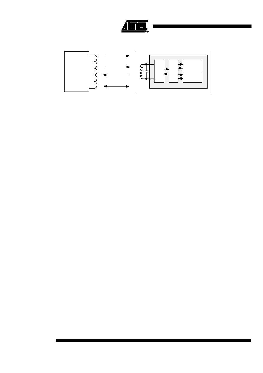
The e5561 is a member of Atmel's IDentification IC (IDIC) family for applications
where information has to be transmitted contactlessly. The IDIC is connected to a
tuned LC circuit for power supply and bi-directional data communication (Read/Write)
to a base station. Atmel offers an LC circuit and a chip assembled in the form of a tran-
sponder or tag. These units are small, smart and rugged data storage units.
The e5561 is a Read/Write crypto IC for applications which demand higher security
levels than standard R/W transponder ICs can offer. For that purpose, the e5561 has
an encryption algorithm block which enables a base station to authenticate the tran-
sponder. The base station transmits a random number to the e5561. This challenge is
encrypted by both IC and base station. The e5561 sends back the result to the base
station for comparison. As both should possess the same secret key, the results of this
encryption are expected to be equal. Any attempt to fake the base station with a wrong
transponder will be recognized immediately.
The on-chip 320-bit EEPROM (10 blocks of 32 bits each) can be read and written
blockwise by a base station. Two or four blocks contain the ID code and six memory
blocks are used to store the crypto key as well as the read/write options. The crypto
key and the ID code can be protected individually against overwriting. Likewise, the
crypto key cannot be read out.
125 kHz is the typical operational frequency of a system using the e5561. Two read
data rates are programmable. Reading occurs through damping the incoming RF field
with an on-chip load. This damping is detected by the field-generating base station.
Data transmission starts after power-up with the transmission of the ID code and con-
tinues as long as the e5561 is powered. Writing is carried out with Atmel's writing
method. To transmit data to the e5561, the base station has to interrupt the RF for a
short time to create a field gap. The information is encoded in the number of clock
cycles between two subsequent gaps.
Standard
Read/Write
Crypto
Identification IC
e5561
Rev. 4699A≠RFID≠04/03
2
e5561
4699A≠RFID≠04/03
Figure 1. Transponder System Example Using e5561
Internal Modes
The e5561 can be operated in several internal modes, each providing a special function.
These are:
∑
Start-up
∑
ID mode
∑
Programming mode
∑
Direct-access mode
∑
Crypto mode
∑
Stop mode
∑
Password function
The following section gives a short functional description of each mode. A more detailed
description is given in the section "Operating the e5561".
Start-up
After the Power-On Reset (POR) has reset the entire circuit, the e5561 is configured by
reading out the configuration data bits of the EEPROM.
ID Mode
During ID mode, the e5561 transmits an identification data stream (ID code) to the base
station. As the base station reads out data coming from the transponder, this direction of
data transmission will be designated as 'read'.
The ID code is sent in loop as long as the RF field is applied. The single parts of the data
stream and the type of modulation depend on the configuration loaded during start-up.
The following options are available during ID mode:
∑
Two different bit rates and modulations
∑
Two possible lengths of the ID code (64 bits or 128 bits)
∑
Two different terminators
∑
A 4-bit preburst followed by terminator 1 between start-up and sending the first data
bits of the ID code
Programming Mode
The e5561 must be programmed before being used in a security system. The e5561
contains a 320-bit EEPROM which is arranged in 10 blocks of 32 bits each. Program-
ming the e5561 is carried out blockwise, i.e., every single block has to be programmed
separately. The blocks of the EEPROM are divided into 4 sections:
∑
Configuration
∑
ID code
∑
Crypto key
∑
Customer configuration
e5561
C
o
n
t
r
o
l
l
e
r
C
o
i
l
i
n
t
e
r
f
a
c
e
Memory
Transponder
Base
Data
Power
Response
Challenge
Crypto
station

3
e5561
4699A≠RFID≠04/03
Every section consists of one or more EEPROM blocks. Programming is carried out by
sending the programming data sequence to the e5561. When the base station sends
data to the transponder, this direction of data transmission will be designated as 'write'.
When the base station has sent the data sequence and the specified block has been
programmed, the e5561 transmits the content of the programmed EEPROM block. The
content is always sent in loop with terminator 1. The beginning of the data stream is indi-
cated by a preburst.
During programming, the e5561 monitors several fault and protection mechanisms. If a
fault or a protection violation is detected, the e5561 switches to ID mode.
Direct-access Mode
If the base station transmits a special data sequence to the e5561, it will enter the direct-
access mode. The base station can activate two different functions:
∑
Read the content of a single block of the EEPROM
In this case, the e5561 transmits the block's content in loop, starting with a preburst
followed by the terminator which is also used to indicate the beginning of the trans-
mission of the specified block data.
∑
Reset the e5561 in case of all modes
During direct-access mode, the e5561 monitors several fault and protection mecha-
nisms. If a fault or a protection violation is detected, the e5561 switches to ID mode.
Crypto Mode
In crypto mode, a non-linear high-security encryption algorithm called AUT64 is used to
authenticate the e5561.
After the base station has identified the e5561 (i.e., read the ID code), the base station
may authenticate the transponder by transmitting a challenge. Receiving this data
sequence causes the e5561 to switch to crypto mode.
This initiates the following actions:
∑
While calculating the AUT64 result, the transponder transmits the checksum of the
challenge
∑
The e5561 generates the response from the calculated result of the AUT64
∑
As soon as the calculation is finished, the e5561 interrupts the transmission of the
checksum by sending a terminator
∑
The e5561 transmits the response in loop with a terminator back to the base station
The base station can read the response and authentify the transponder. It is possible to
interrupt the calculation of the AUT64 result by sending another data sequence (e.g., if
the checksum was found to be wrong).
During crypto mode, the e5561 monitors several fault and protection mechanisms. If a
fault or a protection violation is detected, the e5561 enters ID mode.
Stop Mode
If two or more transponders are used simultaneously (e.g., in a manufacturing step), it
might be useful to be able to set the transponders to a passive state. To avoid a commu-
nication conflict, the base station has to transmit a special data sequence to the active
transponder(s) forcing them to switch to stop mode.
In stop mode, the e5561 switches off the damping as long as the RF field is applied.
After a power-on reset or after having received the software-reset command, the e5561
enters start-up and ID mode again.
During the data sequence of the stop mode, the e5561 monitors fault mechanisms. If a
fault is detected, the e5561 enters ID mode.
4
e5561
4699A≠RFID≠04/03
The stop command can be disabled.
Note:
For correct stop-mode operation it is necessary that the field be switched off instantly.
Password Function
The password function is a separate protection mechanism to prevent a base station
from reading or manipulating the internal configuration and data blocks of the e5561
without knowing the password. Only a transition to the crypto mode is possible. If the
password function is active, the base station must first send the password to enable any
other operations.
During password mode, the e5561 monitors several fault and protection mechanism. If a
fault or a protection violation is detected, the e5561 enters ID mode.
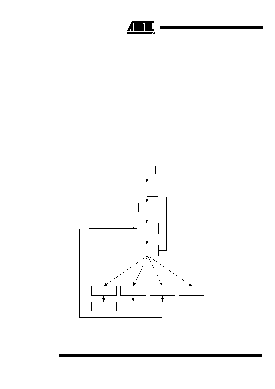
Mode Transitions
If the e5561 is in ID mode and the base station transmits a write sequence by interrupt-
ing the RF field, the internal mode changes according to the received write sequence. If
an error has been detected or the password function has been enabled, the e5561
remains in ID mode.
A transition to and from all other modes (except the ID mode) is possible by sending the
corresponding write sequence. Once the ID mode is left, switching to another mode is
only possible by sending an uncorrect data sequence to the transponder.
Figure 2. State Diagram of the e5561 (Overview)
Note:
This diagram provides only an overview. In reality, more transitions are possible.
Reset
Start-up
ID mode
Sequence
received
Crypto mode
Programming
mode
Direct-access
mode
Stop mode
Password
function
Gap
Error
Transmit data
Transmit data
Transmit data
Gap
5
e5561
4699A≠RFID≠04/03
Building Blocks
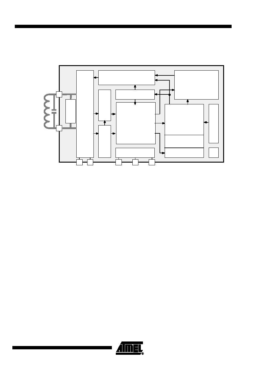
Figure 3. Block Diagram
Analog Front End (AFE)
The AFE includes all circuits directly connected to the coil. It generates the IC's power
supply and handles the bi-directional data communication with the base station. It con-
sists of the following blocks:
∑
Rectifier to generate a DC supply voltage from the AC coil voltage
∑
Clock extractor
∑
Switchable load between Coil1/Coil2 for data transmission from the IC to the base
station (read)
∑
Field gap detector for data transmission from the base station to the IC (write)
Controller
The controller has the following functions:
∑
Initialize and refresh the EEPROM's configuration register
∑
Control memory access (read, program)
∑
Handle correct write data transmission
∑
Error detection and error handling
∑
Control encryption operation
∑
Control the adaptation of resonance frequency
Power-On Reset (POR)
The power-on reset is a delay reset which is triggered when the supply voltage is
applied.
Configuration Register
The configuration register stores the configuration data read out from EEPROM blocks 0
and 9. It is continuously refreshed which increases the reliability of the device (if the ini-
tially loaded configuration was wrong or modified, it will be corrected by subsequent
refresh cycles).
Configuration data
Transmission
EEPROM control
Error detection
Encryption
Coil1
Coil2
Modulator
A
n
a
l
o
g
F
r
o
n
t
E
n
d
Input register
B
i
t
d
e
c
o
d
e
r
B
i
t
r
a
t
e
g
e
n
e
r
a
t
o
r
64- or 128-bit code
CONTROLLER
Conf. register
H
V
G
e
n
e
r
a
t
o
r
V
DD
Crypto circuit
POR
Test pads
Crypto key
Memory
A
d
a
p
t
EEPROM
Test logic
V
SS