 | –≠–ª–µ–∫—Ç—Ä–æ–Ω–Ω—ã–π –∫–æ–º–ø–æ–Ω–µ–Ω—Ç: SAM9707 | –°–∫–∞—á–∞—Ç—å:  PDF PDF  ZIP ZIP |

1
Features
∑
Single-chip Sound Studio with Typical Applications including:
≠ Wavetable Synthesis, Serial MIDI In & Out, MPU-401 (UART)
≠ Game-compatible Synthesis with Adlib Interface
≠ Effects: Reverb and Chorus
≠ Directsound
TM
, Direct3Dsound
TM
Accelerator with Static Buffer Support
≠ Interactive 3-D Positioning
≠ Four-channel Surround
≠ Four-band Equalizer
≠ Mixer
∑
High-quality Wavetable Synthesis
≠ 16-bit Samples with up to 48 kHz Sampling Rate
≠ Internal Computations on 28 Bits, DAC Support up to 20 Bits
≠ Alternate Loop, 24 dB Digital Filter for Each Voice
∑
Professional Effects
≠ 13 Delay Lines for Resonance-free Stereo Reverb
∑
Four-band Final Equalizer Allows Dramatic Sound presence Improvement
∑
Expandable
≠ Minimum System: ATSAM9707 + 512K Bytes of ROM + 32K x 8 RAM + DAC
≠ Maximum System: ATSAM9707 + 64M Bytes of DRAM + Codec + DAC
∑
High Performance
≠ RISC Structure for Sound Synthesis/Processing
≠ CISC Structure for Host Communication and Housekeeping
≠ Audio Transfer at Maximum 16-bit ISA Bus Speed
≠ Audio Transfer in Burst Mode: Removes DMA-controlled Transfer Burden
∑
Fully Programmable
≠ Firmware Downloaded to Memory at Power-up. Easy Software Upgrade.
≠ Chip Programming Open to Third-party Software Companies
≠ Powerful Programming and Debugging Tools: Algorithm Compiler, Sound Editor,
Assembler and Source Debugger. Direct Development from PC Environment, No
Special Emulator Required
∑
Top Technology
≠ Single Low-frequency Crystal Operation and Built-in PLL Minimize RFI
≠ 144-lead TQFP Space-saving Package
∑
Pin and Function Compatible with ATSAM9407 with Additional Features for
Professional Use:
≠ Up to Eight Channels of Audio-in
≠ Improved Digital Mix Levels and Digital Overflow Handling
≠ Improved Tuning Accuracy
≠ Additional DSP Micro-instructions and Datapath for More Efficient
Audio Processing Algorithm Coding
Note:
Pin-to-pin replacement for ATSAM9407 requires 3.3V core supply V
C3
.
Description
The ATSAM9707 is a highly integrated sound processor studio that combines a spe-
cialized high-performance RISC-based digital signal processor (synthesis/DSP) and a
general-purpose 16-bit CISC-based control processor on a single chip. An on-chip
memory management unit (MMU) allows the synthesis/DSP and the control processor
to share external ROM and/or RAM memory devices. An intelligent peripheral I/O
interface function handles other I/O interfaces, such as the ISA PC bus, the on-chip
MIDI UART and the codec control interface, with minimum intervention from the con-
trol processor.
Sound
Synthesis
ATSAM9707
Integrated
Sound Studio
Rev. 1711B-DRMSD≠11/02
2
ATSAM9707
1711B≠DRMSD≠11/02
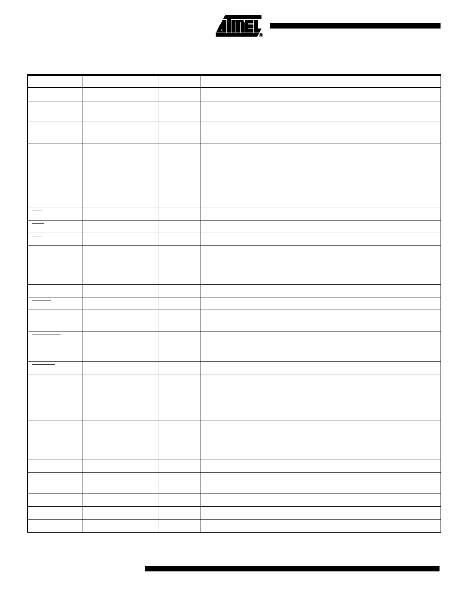
Pin Description
Table 1. Pins by Function
Pin Name
Pin Count
Type
Function
GND
17
PWR
Power ground ≠ All GND pins should be returned to digital ground.
V
C3
3
PWR
Core power +3.3V nominal (3V to 4.5V). All V
C3
pins should be returned to
+3.3V.
V
CC
15
PWR
Power +3V to +5.5V ≠ All V
CC
pins should be returned to +5V (or 3.3V in
case of single 3.3V supply).
D[15:0]
16
I/O
16-bit data bus to host processor. Has enough driving power to drive ISA PC
bus directly (24 mA buffer).
Information on these pins is:
- parallel MIDI (MPU-401 type applications)
- Adlib control (game sound-type emulation)
- Down-/upload of PCM data or application programs
Direct ISA PC bus drive requires 5V V
CC
.
CS
1
IN
Chip select from host, active low
WR
1
IN
Write from host, active low
RD
1
IN
Read from host, active low
A[1:0]
3
IN
Selects one of eight internal registers
- 0, 1: MPU-401 registers
- 2, 3: 16-bit data (burst DMA mode)
- 4-7: game sound registers
IRQ
1
TSout
Tri-state output pin. Can be connected directly to host IRQ line (24 mA).
SBHE
1
IN
Bus high enable signal, active low. Normally connected to GND.
I/O READY
1
OUT
Open drain output buffer (24 mA); driven low during 16-bit burst mode
transfers to synchronize PC to the ATSAM9707 memory.
I/O CS16
1
OUT
Open drain output buffer (24 mA); driven low during 16-bit burst mode
transfers.
Indicates to host that a 16-bit I/O is in progress.
RESET
1
IN
Master reset input, active low. Schmitt trigger input.
X1
X2
2
Crystal connection. Crystal frequency should be f
S
x256 (typ 11.2896 MHz).
Crystal frequency is internally multiplied by four to provide the IC master
clock.
X1 can also be used as external clock input (3.3V input).
X2 CANNOT BE USED TO DRIVE EXTERNAL CIRCUITRY.
DABD[1:0]
2
OUT
Two stereo serial audio data outputs (four audio channels). Each output
holds 64 bits (2 x 32) of serial data per frame. Audio data has precision of up
to 20 bits. DABD0 can hold additional control data (mute, A/D gain, D/A gain,
etc.).
CLBD
1
OUT
Audio data bit clock; provides timing to DABD061.
WSBD
1
OUT
Audio data word select. The timing of WSBD can be selected to be I2S or
Japanese compatible.
DAAD
1
IN
Stereo serial audio data input
MIDI_IN
1
IN
Serial MIDI_IN input
MIDI_OUT
1
OUT
Serial MIDI_OUT output

3
ATSAM9707
1711B≠DRMSD≠11/02
Note:
Pin names with an overbar (RAS for example) indicate that the signal is active low.
WA[24:0]
25
OUT
External memory address (ROM/SRAM). Up to 32M words (64M 8-bit
samples).
WD[15:0]
16
I/O
PCM ROM/SRAM/DRAM data
RBS
1
OUT
SRAM byte select: Should be connected to the lower RAM address when 8-
bit wide SRAM is used. The type of RAM (16 bits/8 bits) can be selected by
program.
WCS0
1
OUT
PCM ROM chip select, active low.
WCS1
1
OUT
SRAM chip select, active low.
WWE
1
OUT
SRAM/DRAM write enable, active low. Timing compatible with SIMM DRAM
early write feature.
WOE
1
OUT
PCM ROM/SRAM output enable, active low.
BOOT
1
IN
Active high, specifies that built-in CPU bootstrap should be used at power-up
(case of DRAM connection only).
DRA[11:0]
12
OUT
Multiplex DRAM address: 9-, 10-, 11-, 12-bit multiplex addressing can be
used (from 256K x 16- to 16M x 16-type configurations).
RAS
1
OUT
DRAM row address strobe
CAS
1
OUT
DRAM column address strobe
P[3:0]
4
I/O
General-purpose configurable I/O pins. P1 to P3 can be configured as three
additional stereo serial audio data inputs, providing the DAAD with up to
eight channels of audio-in.
S[1:0]
2
OUT
Indicates type of external memory cycle.
S1S0 = 01: Idle or refresh, 00: Synthesis access, 10: Instruction fetch,
11: Processor read/write
RUN
1
OUT
High when the synthesis is initialized. Can be used as RESET for an external
device (CODEC).
LFT
1
ANA
PLL low pass filter. Should be connected to an external RC network test pin;
should be returned to GND.
TEST[2:0]
3
IN
Test pins; should be returned to GND.
PDWN
1
IN
Power-down, active low.
Table 1. Pins by Function (Continued)
Pin Name
Pin Count
Type
Function
4
ATSAM9707
1711B≠DRMSD≠11/02
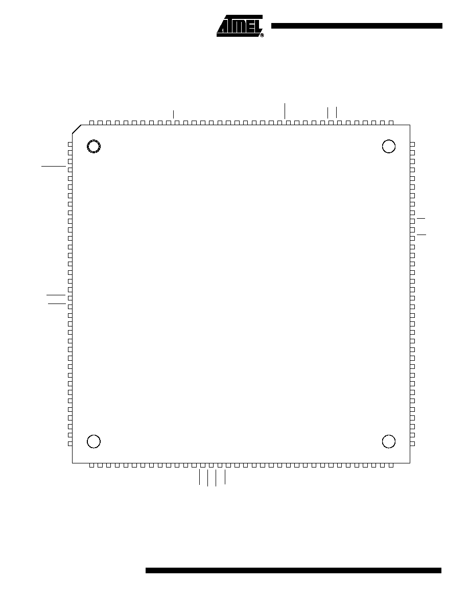
Pinout
Figure 1. ATSAM9707 in 144-lead TQFP Package
VCC
IRQ
GND
I/O CS16
WD13
MIDI OUT
WD14
DRA0
DRA1
WD15
GND
VCC
GND
VC3
VC3
LFT
X2
X1
RESET
PDWN
VCC
GND
DRA2
CRA3
MIDI IN
RUN
DRA4
VC3
GND
VCC
GND
D0
CLBD
VC3
D1
RBS
GND
D11
VCC
D10
WA18
WA17
A2
A1
GND
RD
VCC
WR
WA16
WA15
WA14
WA13
WA12
WA11
WA10
A0
WA9
WA8
WA7
GND
D9
VCC
D8
WA6
WA5
WA4
WA3
GND
D7
VCC
D6
WA2
BOOT
D2
VCC
D3
GND
DRA5
DAAD
DRA6
DABD0
DRA7
DRA8
DABD1
WSBD
WWE
WCS0
WCS1
WOE
VCC
DRA9
GND
P0
P1
P2
P3
TEST0
TEST1
TEST2
GND
DRA10
WA0
DRA11
VCC
D4
GND
D5
WA1
WD12
D15
WD11
D14
WD10
S1
WD9
WD8
S0
VCC
CS
GND
WD7
WD6
WD5
WD4
WD3
I/O READY
WD2
WD1
WD0
WA24
WA23
SBHE
GND
GND
VCC
WA22
RAS
CAS
WA21
WA20
D13
VC13
D12
WA19
1
2
3
4
5
6
7
8
9
10
11
12
13
14
15
16
17
18
19
20
21
22
23
24
25
26
27
28
29
30
31
32
33
34
35
36
108
107
106
105
104
103
102
101
100
99
98
97
96
95
94
93
92
91
90
89
88
87
86
85
84
83
82
81
80
79
78
77
76
75
74
73
144
143
142
141
140
139
138
137
136
135
134
133
132
131
130
129
128
127
126
125
124
123
122
121
120
119
118
117
116
115
114
113
112
111
110
109
37
38
39
40
41
42
43
44
45
46
47
48
49
50
51
52
53
54
55
56
57
58
59
60
61
62
63
64
65
66
67
68
69
70
71
72
5
ATSAM9707
1711B≠DRMSD≠11/02
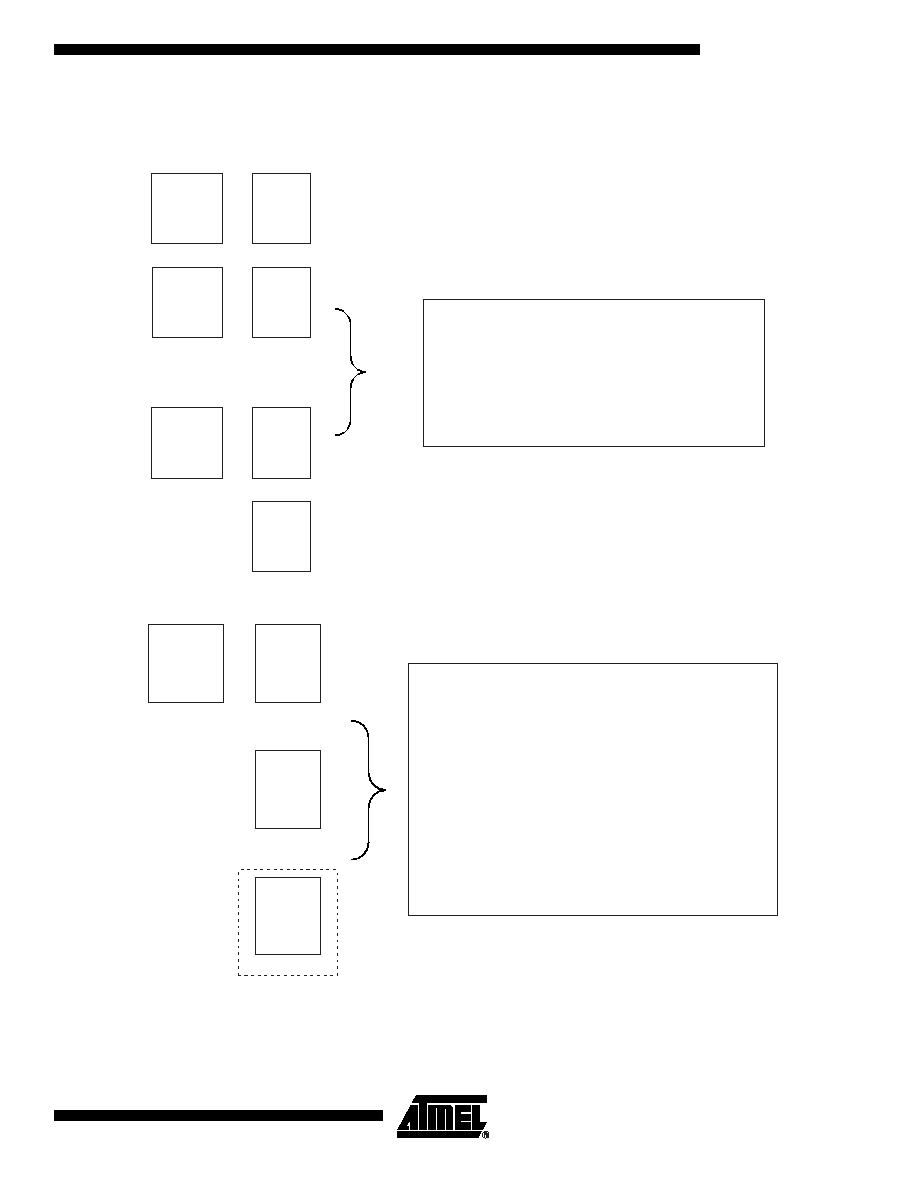
Typical Designs
Figure 2. Lowest Cost Design Architecture
Figure 3. Typical Design Architecture
DRAM
256K x 16
CODEC
CODEC
SRAM
32K x 8
ATSAM9707
ATSAM9707
ROM
256K x 16
or
- General MIDI-compliant Wavetable Synthesis
- Compatible Reverb + Chorus
- Wave Play and Record (One Stereo Channel)
- Game-compatible Synthesis
- 3-D Effect
- Four-band Equalizer
DRAM
1M x 16
ATSAM9707
DAC
Option
CODEC
- Professional-quality General MIDI-compliant Synthesis
- Sound Extensions
- Additional Top-quality Drumsets and Bass
- Compatible Reverb + Chorus
- Downloadable Sounds
- Wave Play and Record up to Eight Stereo Channels
with Interactive 3-D Positioning
- Game-compatible Synthesis
- DirectSound
TM
Static Buffer Support
- 3-D Effect
- Four-channel Surround (option)
- Four-band Equalizer
- Audio-in Effects (Reverb or Echo)