 | –≠–ª–µ–∫—Ç—Ä–æ–Ω–Ω—ã–π –∫–æ–º–ø–æ–Ω–µ–Ω—Ç: T4260IL | –°–∫–∞—á–∞—Ç—å:  PDF PDF  ZIP ZIP |
Rev. 4528G≠AUDR≠12/03
Features
∑
AM/FM Tuner Front End with Integrated PLL
∑
AM Up-conversion System (AM-IF: 10.7 MHz)
∑
FM Down-conversion System (FM-IF: 10.7 MHz)
∑
IF Frequencies up to 25 MHz
∑
Fine-tuning Steps: AM = 1 kHz and FM = 50 kHz/25 kHz/12.5 kHz
∑
Fast Fractional PLL (Lock Time < 1 ms) Inclusive Spurious Compensation
∑
Fast RF-AGC, Programmable in 1-dB Steps
∑
Fast IF-AGC, Programmable in 2-dB Steps
∑
Fast Frequency Change by 2 Programmable N-divider
∑
Two DACs for Automatic Tuner Alignment
∑
High S/N Ratio
∑
3-wire Bus (Enable, Clock and Data; 3 V and 5 V Microcontrollers-compatible)
Description
The T4260 is an advanced AM/FM receiver with integrated fast PLL as a single-chip
solution based on Atmel's high-performance BICMOS II technology. The low-imped-
ance driver at the IF output is designed for the A/D of a digital IF. The fast tuning
concept realized in this part is based on patents held by Atmel and allows lock times
less than 1 ms for a jump over the FM band with a step width of 12.5 kHz. The AM
up-conversion and the FM down-conversion allows an economic filter concept. An
automatic tuner alignment is provided by built-in DACs for gain and offset compensa-
tion. The frequency range of the IC covers the FM broadcasting band as well as the
AM band. The low current consumption helps the designers to achieve economic
power consumption concepts and helps to keep the power dissipation in the tuner low.
Pin Description
Figure 1. Pinning SSO44
D
A
C
1
D
A
C
2
F
M
A
G
C
O
M
X
F
M
I
A
M
X
F
M
I
B
G
N
D
R
F
M
X
A
M
I
B
M
X
A
M
I
A
A
M
A
G
C
O
I
F
A
G
C
A
2
S
W
2
/
A
G
C
R
F
A
G
C
A
2
S
W
1
V
R
V
C
O
V
S
P
L
L
F
M
L
F
A
M
L
F
V
T
U
N
E
O
S
C
G
N
D
O
S
C
E
O
S
C
B
O
S
C
B
U
F
E
N
C
L
K
D
A
T
A
V
R
P
L
L
R
E
F
F
R
E
Q
G
N
D
P
L
L
I
F
O
U
T
B
I
F
O
U
T
A
I
F
A
G
C
F
M
I
F
A
G
C
A
1
R
F
A
G
C
F
M
I
F
R
E
F
I
F
I
N
A
M
I
F
I
N
F
M
V
R
T
G
N
D
T
M
X
A
M
O
B
M
X
A
M
O
A
V
S
T
R
F
A
G
C
A
1
M
X
F
M
O
A
M
X
F
M
O
B
1
2
3
4
5
6
7
8
9
1
0
1
1
1
2
1
3
1
4
1
5
1
6
1
7
1
8
1
9
2
0
2
1
2
2
4
4
4
3
4
2
4
1
4
0
3
9
3
8
3
7
3
6
3
5
3
4
3
3
3
2
3
1
3
0
2
9
2
8
2
7
2
6
2
5
2
4
2
3
AM/FM
Front End IC
T4260

2
T4260
4528G≠AUDR≠12/03
Pin Description
Pin
Symbol
Function
1
DAC1
DAC1 output
2
DAC2
DAC2 output
3
FMAGCO
FM AGC current
4
MXFMIA
FM mixer input A
5
MXFMIB
FM mixer input B
6
GNDRF
RF ground
7
MXAMIB
AM mixer input B
8
MXAMIA
AM mixer input A
9
AMAGCO
AM AGC current
10
IFAGCA2
AM IF-AGC filter 2
11
SW2/AGC
Switch 2 / AM AGC voltage
12
RFAGCA2
RF AM-AGC filter 2
13
SW1
Switching output 1
14
VRVCO
VCO reference voltage
15
VSPLL
PLL supply voltage
16
FMLF
FM loop filter
17
AMLF
AM loop filter
18
VTUNE
Tuning voltage
19
OSCGND
Oscillator ground
20
OSCE
Oscillator emitter
21
OSCB
Oscillator base
22
OSCBUF
Oscillator buffer output/input
23
EN
3-wire bus Enable
24
CLK
3-wire bus Clock
25
DATA
3-wire bus Data
26
VRPLL
PLL reference voltage
27
REFFREQ
PLL reference frequency
28
GNDPLL
PLL ground
29
IFOUTB
IF output B
30
IFOUTA
IF output A
31
IFAGCFM
FM IF-AGC filter
32
IFAGCA1
AM IF-AGC filter 1
33
RFAGCFM
RF FM-AGC filter
34
IFREF
IF amplifier reference input
35
IFINAM
IF amplifier AM input
36
IFINFM
IF amplifier FM input
37
VRT
Tuner reference voltage
38
GNDT
Tuner ground
39
MXAMOB
AM mixer output B
40
MXAMOA
AM mixer output A
41
VST
Tuner supply voltage
42
RFAGCA1
RF AM-AGC filter 1
43
MXFMOA
FM mixer output A
44
MXFMOB
FM mixer output B

3
T4260
4528G≠AUDR≠12/03
Figure 2. Block Diagram
Functional
Description
The T4260 implements an AM up-conversion reception path from the RF input signal to
the IF output signal. A VCO and an LO prescaler for AM are integrated to generate the
LO frequency to the AM mixer. The FM reception path generates the same LO
frequency from the RF input signal by a down-conversion to the IF output. The IF A/D
output is designed for digital signal processing. The IF can be chosen in the range of
10 MHz to 25 MHz. Automatic gain control (AGC) circuits are implemented to control the
preamplifier stages in the AM and FM reception paths.
For improved performance, the PLL has an integrated special 2-bit shift fractional logic
with spurious suppression that enables fast frequency changes in AM and FM mode by
a low step frequency (f
PDF
). In addition, two programmable DACs (Digital to Analog
Converter) support the alignment via a microcontroller.
For a double-tuner concept, external voltage can be applied at the input of the DACs,
the internal PLL can switched off and the OSC buffer (output) can also be used as input.
Several register bits (Bit 0 to Bit 145) are used to control the circuit's operation and to
adapt certain circuit parameters to the specific application. The control bits are orga-
nized in four 8-bit, four 16-bit and three 24-bit registers that can be programmed by the
3-wire bus protocol. The bus protocol and the bit-to-register mapping is described in the
section "3-wire Bus Description" on page 9. The meaning of the control bits is mentioned
in the following sections.
AGC
PLL
SUPPLY
AGC
DIV
N DIV
R DIV
PD
RF/IF
SUPPLY
BUS
VCO
FMAGCO
GNDRF
MXAMIB
MXAMIA
MXFMIB
MXFMIA
AMAGCO
AM
FM
43
MXFMOB
MXAMOB
MXAMOA
IFREF
IFINAM
ININFM
IFOUTB
IFOUTA
IFAGCFM
IFAGCA1
VST
VRT
GNDT
VSPLL
VRPLL
GNDPLL
EN
CLK
DATA
SW1
SW2/AGC
VTUNE
AMLF
FMLF
REFFREQ
OSCGND
OSCE
OSCB
OSCBUF
RFAGCA2
RFAGCFM
RFAGCA1
VRVCO
DAC1
DAC2
IFAGCA2
SW-AMLF
MXFMOA
44
39
40
34
35
36
29 30
31 10
32
41
37
38
14
15
26
28
23
24
25
11
13
2
1
16
17
18
22
21 20 19
27
4
5
6
7
8
42
33
12
9
3
4
T4260
4528G≠AUDR≠12/03
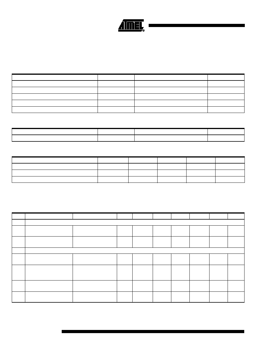
Absolute Maximum Ratings
Stresses beyond those listed under "Absolute Maximum Ratings" may cause permanent damage to the device. This is a stress rating
only and functional operation of the device at these or any other conditions beyond those indicated in the operational sections of this
specification is not implied. Exposure to absolute maximum rating conditions for extended periods may affect device reliability.
All voltages are referred to GND
Parameters
Symbol
Value
Unit
Analog supply voltage
Pins 15 and 41
V
ST
, V
SPLL
10
V
Maximum power consumption
P
tot
1.0
W
Ambient temperature range
T
amb
-40 to +85
∞
C
Storage temperature range
T
stg
-40 to +150
∞
C
Junction temperature
T
j
150
∞
C
Thermal Resistance
Parameters
Symbol
Value
Unit
Junction ambient, soldered to PCB
R
thJA
52
K/W
Operating Range
Parameters
Symbol
Min.
Typ.
Max.
Unit
Supply voltage range
(1)
Pins 15 and 41
V
ST
, V
SPLL
8
8.5
10
V
Ambient temperature
T
amb
-40
85
∞
C
Oscillator frequency
Pin 21
R
fi
60
175
MHz
Note:
1. V
ST
and V
SPLL
must have the same voltage.
Electrical Characteristics
Test conditions (unless otherwise specified): V
ST
/V
SPLL
= +8.5 V, T
amb
= +25
∞
C
No.
Parameters
Test Conditions
Pin
Symbol
Min.
Typ.
Max.
Unit
Type*
1
Power Supply
1.1
Supply voltage
15,
41
V
S
8
8.5
10
V
C
1.2
Supply current
AM and FM mode,
V
S
= 10 V
15,
41
I
S
70
85
110
mA
A
2
PLL Divider
2.1
Programmable
R-divider
14-bit register
3
16383
A
2.2
Programmable (VCO)
N-divider
(1 kHz step frequency)
2-
◊
18-bit register
switchable via Bit 5
3
262143
A
2.3
Reference oscillator
input voltage
f = 0.1 MHz to 3 MHz
27
100
mV
rms
B
2.4
Reference frequency
FM
AM
120
120
150
2850
10000
10000
kHz
kHz
*) Type means: A = 100% tested, B = 100% correlation tested, C = Characterized on samples, D = Design parameter
Note:
1. Minimum and maximum limits are characterized for entire temperature range (-40
∞
C to +85
∞
C) but are tested at +25
∞
C

5
T4260
4528G≠AUDR≠12/03
2.5
Settling time in FM
mode (switching from
87.5 MHz to 108 MHz
or vice versa)
f
PD
= 50 kHz
I
PD
= 2 mA
1
ms
B
3
AMLF/FMLF
3.1
Output current 1
FMLF, AMLF = 1.8 V
16,
17
40
50
60
µA
A
(1)
3.2
Output current 2
FMLF, AMLF = 1.8 V
16,
17
80
100
120
µA
A
(1)
3.3
Output current 3
FMLF, AMLF = 1.8 V
16,
17
850
1000
1250
µA
A
(1)
3.4
Output current 4
FMLF, AMLF = 1.8 V
16,
17
1650
2000
2450
µA
A
(1)
3.5
Leakage current
FMLF, AMLF = 1.8 V
16,
17
10
nA
A
(1)
4
VTUNE
4.1
Saturation voltage
LOW
V
SATH
= (V
A
-V
PDOFM
)
18
V
SATL
100
200
400
mV
C
4.2
Saturation voltage
HIGH
V
SATH
= (V
A
-V
PDOFM
)
18
V
SATH
500
mV
C
5
DAC1, DAC2
5.1
Output current
1, 2
I
DAC1,2
1
mA
D
5.2
Output voltage
1, 2
V
DAC1,2
0.3
V
S
-0.6
V
A
5.3
Maximum offset range
Offset = 0, gain = 58
1, 2
0.9
0.98
1.1
V
A
(1)
5.4
Minimum offset range
Offset = 127, gain = 58
1, 2
-0.9
-0.98
-1.1
V
A
(1)
5.5
Maximum gain range
Gain = 255, offset = 64
1, 2
2.06
2.09
2.13
≠
A
(1)
5.6
Minimum gain range
Gain = 0, offset = 64
1, 2
0.63
0.67
0.73
≠
A
(1)
6
Oscillator
6.1
Frequency range
21
60
170
MHz
B
6.2
Fractional frequency
range
Fractional mode
21
60
140
MHz
A
6.3
Buffer output
22
150
mV
rms
C
7
Oscillator Input
7.1
Input voltage
21
V
OSC
150
mV
rms
A
8
FM Mixer
8.1
Frequency range
75
163
MHz
B
8.2
Input IP3
133
dBµV
C
8.3
Input impedance
3.5
k
D
8.4
Input capacitance
4
pF
D
8.5
Noise figure
F
14
dB
C
8.6
Conversion
transconductance
2.6
3.1
3.6
ms
D
(1)
Electrical Characteristics (Continued)
Test conditions (unless otherwise specified): V
ST
/V
SPLL
= +8.5 V, T
amb
= +25
∞
C
No.
Parameters
Test Conditions
Pin
Symbol
Min.
Typ.
Max.
Unit
Type*
*) Type means: A = 100% tested, B = 100% correlation tested, C = Characterized on samples, D = Design parameter
Note:
1. Minimum and maximum limits are characterized for entire temperature range (-40
∞
C to +85
∞
C) but are tested at +25
∞
C