1
4726A≠AUTO≠06/03
Features
∑
Temperature and Supply Voltage Compensated Flashing Frequency
∑
Frequency Doubling Indicates Lamp Outage
∑
Relay Driver Output with High Current Carrying Capacity and Low Saturation Voltage
∑
Minimum Lamp Load for Flasher Operation:
≥
1 W
∑
Very Low Susceptibility to EMI
∑
Protection According to ISO/TR 7637/1 Level 4
Description
The bipolar integrated circuit U6043B is used in relay-controlled automotive flashers
where a high level EMC is required.
Lamp outage is indicated by frequency doubling during hazard warning as well as
direction mode.
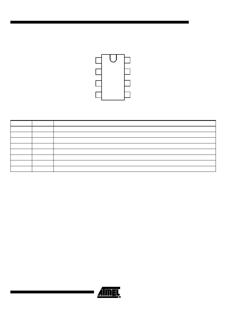
Flasher IC with
18-m
W
Shunt
U6043B

4
U6043B
4726A≠AUTO≠06/03
Functional Description
Pin 1, GND
The U6043B is protected against damage in case of battery reversal via resistor R
4
to
ground (-31). An integrated protection circuit together with external resistances R
2
and
R
4
limits the current pulses in the IC.
Pin 2, Supply Voltage,
V
S
power
The arrangement of the supply connections to Pin 2 (and 6) must be so as to ensure
that on the connection printed circuit board (PCB), the resistance of V
S
to Pin 6 is lower
than that to Pin 2.
Pin 3, Relay Control
Output (Driver)
The relay control output is a high-side driver with a low saturation voltage. It is capable
of driving a typical automotive relay with a minimum coil resistance of 60
W
.
Pin 4 and 5, Oscillator
The flashing frequency, f
1
, is determined by the R
1
C
1
components as given by the fol-
lowing formula below (see Figure 1):
where C
1
£
47 µF, R
1
= 6.8 k
W
to 510 k
W
In case of a lamp outage (see Pin 7) the oscillator frequency is switched to the lamp out-
age frequency f
2
with f
2
ª
2.2
¥
f
1
.
Duty cycle in normal flashing mode: 50%
Duty cycle in lamp outage mode: 40% (bright phase)
Pin 6, Supply Voltage,
Sense
For accurate monitoring via the shunt resistor, a minimized layer resistance from point
V
S
/shunt to Pin 6 is recommended.
Pin 7, Lamp Outage
Detection
The lamp current is monitored via an external shunt resistor R
sh
and an internal compar-
ator K1 with its reference voltage of typ. 49 mV (V
S
= 12 V). The outage of one lamp is
detected according to the following calculation:
Nominal current of 1 lamp: 21 W/(V
S
= 12 V): I
lamp
= 1.75 A
Nominal current of 2 lamps: 2
¥
21 W/(V
S
= 12 V): I
lamp
= 3.5 A
We recommend setting the detection threshold in the middle of the current range:
I
outage
ª
2.7 A
Thus, the shunt resistor is calculated as:
R
sh
= V
T
(K1)/I
outage
R
sh
= 49 mV/2.7 A = 18 m
W
Comparator K1's reference voltage is matched to the characteristics of filament lamps
(see "Control Signal Threshold" in the data part).
The combination of shunt resistor and resistance of wire harness prevents Pin 7 from a
too high voltage in case of shorted lamps.
f
1
1
R
1
C
1
¥
1.5
¥
-----------------------------------
Hz
ª

5
U6043B
4726A≠AUTO≠06/03
Pin 8, Start Input
Start condition for flashing: the voltage at Pin 8 has to be below the K3 threshold (flasher
switch closed).
Humidity and dirt may decrease the resistance between 49 a and GND. If this leakage
resistance is > 5 k
W
, the IC is still kept in the off-condition. In this case the voltage at
Pin 8 is between the thresholds of comparators K2 and K3.
During the bright phase the voltage at Pin 8 is above the K2 threshold, during the dark
phase it is below the K3 threshold. For proper start conditions a minimum lamp wattage
of 1 W is required.
Absolute Maximum Ratings
Reference point Pin 1
Parameters
Symbol
Value
Unit
Supply voltage
Pin 2 and 6
V
S
16.5
V
Surge Forward Current
t
P
= 0.1 ms
t
P
= 300 ms
t
P
= 300 ms
Pin 2 and 6
Pin 2 and 6
Pin 8
I
FSM
I
FSM
I
FSM
1.5
1.0
50
A
A
mA
Output current
Pin 3
I
O
0.3
A
Power Dissipation
T
amb
= 95
∞
C
T
amb
= 60
∞
C
DIP 8
SO8
DIP 8
SO8
P
tot
P
tot
P
tot
P
tot
420
340
690
560
mW
mW
mW
mW
Junction temperature
T
J
150
∞
C
Ambient temperature range
T
amb
-40 to +95
∞
C
Storage temperature range
T
stg
-55 to +150
∞
C
Thermal Resistance
Parameters
Symbol
Value
Unit
Junction ambient
DIP8
SO8
R
thJA
R
thJA
110
160
K/W
K/W