KSD-T0C061-000
1
2N5551CN
NPN Silicon Transistor
Descriptions
∑ General purpose amplifier
∑ High voltage application
Features
∑ High collector breakdown voltage : V
CBO
= 180V, V
CEO
= 160V
∑ Low collector saturation voltage : V
CE(sat)
=0.5V(MAX.)
Ordering
Information
Type NO.
Marking
Package Code
2N5551CN 2N5551C
TO-92N
Outline Dimensions unit :
mm
S
S
e
e
m
m
i
i
c
c
o
o
n
n
d
d
u
u
c
c
t
t
o
o
r
r
PIN Connections
1. Emitter
2. Collector
3. Base
3
.
0
9
~
3
.
2
9
0.40 Max.
1.27 Typ.
4
.
2
0
~
4
.
4
0
0.52 Max.
2.25 Max.
1
3
.
5
0
~
1
4
.
5
0
4.20~4.40
2
.
1
4
T
y
p
.
0.90 Max.
3.55 Typ
2 3
1

KSD-T0C061-000
2
2N5551CN
Absolute Maximum Ratings
(Ta=25
∞C)
Characteristic Symbol
Rating
Unit
Collector-base voltage
V
CBO
180 V
Collector-emitter voltage
V
CEO
160 V
Emitter-base voltage
V
EBO
6 V
Collector current
I
C
600
mA
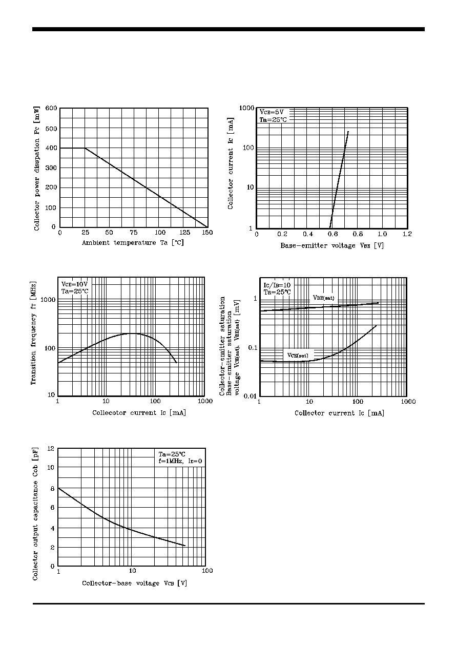
Collector power dissipation
P
C
400
mW
Junction temperature
T
J
150 ∞C
Storage temperature range
T
stg
-55~150 ∞C
Electrical Characteristics
(Ta=25
∞C)
Characteristic Symbol
Test
Condition
Min.
Typ.
Max.
Unit
Collector-emitter breakdown voltage
BV
CEO
I
C
=1mA, I
B
=0 160
-
-
V
Collector cut-off current
I
CBO
V
CB
=180V, I
E
=0 -
-
100
nA
Emitter cut-off current
I
EBO
V
EB
=6V, I
C
=0 -
-
100
nA
DC current gain
h
FE (1)
V
CE
=5V, I
C
=1mA 80
-
-
DC current gain
h
FE (2)
V
CE
=5V, I
C
=10mA 80
-
250
-
DC current gain
h
FE (3)
V
CE
=5V, I
C
=50mA 30
-
-
Collector-emitter saturation voltage
V
CE(sat)(1)
*
I
C
=10mA, I
B
=1mA -
-
0.2
V
Collector-emitter saturation voltage
V
CE(sat)(2)
*
I
C
=50mA, I
B
=5mA -
-
0.5
V
Base-emitter saturation voltage
V
BE(sat)(1)
*
I
C
=10mA, I
B
=1mA -
-
1
V
Base-emitter saturation voltage
V
BE(sat)(2)
*
I
C
=50mA, I
B
=5mA -
-
1
V
Base-emitter voltage
V
BE
V
CE
=5V, I
C
=10mA -
0.65
0.85
V
Transition frequency
f
T
V
CE
=10V, I
C
=10mA -
150
-
MHz
Collector output capacitance
C
ob
V
CB
=10V, I
E
=0, f=1MHz
-
3
-
pF
* : Pulse Tester : Pulse Width 300
µs, Duty Cycle 2.0%

KSD-T0C061-000
4
2N5551CN
The AUK Corp. products are intended for the use as components in general electronic
equipment (Office and communication equipment, measuring equipment, home
appliance, etc.).
Please make sure that you consult with us before you use these AUK Corp. products
in equipments which require high quality and / or reliability, and in equipments which
could have major impact to the welfare of human life(atomic energy control, airplane,
spaceship, transportation, combustion control, all types of safety device, etc.). AUK
Corp. cannot accept liability to any damage which may occur in case these AUK Corp.
products were used in the mentioned equipments without prior consultation with AUK
Corp..
Specifications mentioned in this publication are subject to change without notice.