 | –≠–ª–µ–∫—Ç—Ä–æ–Ω–Ω—ã–π –∫–æ–º–ø–æ–Ω–µ–Ω—Ç: SL5018P | –°–∫–∞—á–∞—Ç—å:  PDF PDF  ZIP ZIP |
KSI-W004-000
1
SL5018/P
LOW POWER NARROW BAND FM IF
Description
The SL5018/P is designed for use in FM dual conversion communication.
It contains a complete narrow band FM demodulation system operable to less than 2.0V
supply voltage. This low power narrow band FM IF system provides the second converter,
second IF, demodulator. Filter Amp and squelch circuitry for communications and scanning
receivers.
Features
∑
Operating voltage range : 2.0V ~ 8.0V
∑
Low Current consumption I
CC
=4.0mA Typ. (V
CC
=4.0V)
∑
Excellent input sensitivity (-3dB Limiting = 2.0
µ
V
rms
Typ.)
∑
Low number of external parts required
∑
Operating frequency up to 60MHz
Ordering
Information
Type NO.
Marking
Package Code
SL5018
SL5018
SOP16
SL5018P
SL5018
DIP16
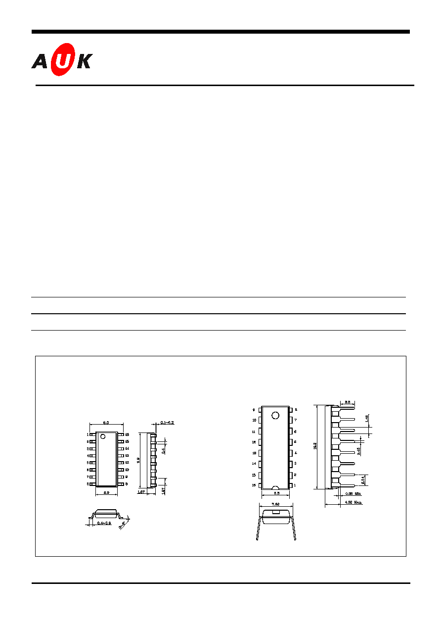
Outline Dmentions
S
S
e
e
m
m
i
i
c
c
o
o
n
n
d
d
u
u
c
c
t
t
o
o
r
r
SOP16
DIP16
KSI-W004-000
2
SL5018/P
Absolute Maximum Ratings
(Ta=25 ∞C)
Characteristics Symbol
Rating
Unit
Maximum Supply Voltage
V
CC(MAX)
10
V
Supply Voltage Range
V
CC
2.0 ~ 8.0
V
Detector input Voltage
V
IN(DET)
1.0 V
p-p
RF Input Voltage(Vcc 4.0V)
V
IN(RF)
1.0 V
rms
Mute Function
V
MUTE
-0.5 ~ +5.0
V
peak
Operating Temperature
T
opr
-20 ~ +70
∞C
Storage Temperature
T
stg
-65 ~ +150
∞C
Electrical Characteristics
(Unless otherwise specified Ta=25 ∞C , Vcc=4V, fo=10.7MHz, fm=1kHz,f = ± 3kHz)
Characteristics
Symbol
Test
Condition
Min. Typ. Max. Unit
I
CC1
Squelch
off(V
12
= 2V)
2.9
3.9
4.9
Squelch Current
(No signal)
I
CC2
Squelch
on(V
12
= 0V)
4.4
5.4
6.4
mA
Audio output Voltage
V
OUT
Vin = 10mVrms
130
160
200 mV
rms
Input Limiting Voltage
V
IN(Lim)
-3dB
Limiting
-
2.0 6.0
Total Harmonic
Distortion
THD V
OUT
= 170mVrms
-
0.8
-
%
Recovered output
Noise Voltage
V
NO
No Input Signal
60
80
250 mV
rms
Drop Voltage AF Gain
Loss
Gv
Vcc = 4V 2V
-3 -0.6 - dB
Detector Output
Resistance
R
OUT
- -
450
-
Signal to Noise Ratio
S/N
-
36
67
-
dB
Filter Gain
G
V
f = 10kHz, Vin = 5mVrms
40
50
-
dB
Filter Output
DC voltage
V
O(DC)
- 1.0
1.3
1.6
V
DC
Mute Low Resistance
R
ON(Mute)
Mute
Switch-on
-
10
-
Mute High Resistance
R
off(Mute)
Mute
Switch-off
1.0 10
-
M
Scan control Low
V
L(Scan)
Mute
off(V
12
= 2V)
-
0
0.4
V
DC
Scan control High
V
H(Scan)
Mute
on(V
12
= 0V)
3.0
3.5
-
V
DC
Trigger Hysteresis
V
TH
Squelch
on/off
- 45 100
mV
rms
Mixer conversion Gain
G
V(Mix)
- -
28
-
dB
Mixer Input Resistance
R
i(Mix)
- -
3.3
-
k
Mixer Input Capacitance
C
i(Mix)
- -
2.2
-
pF
KSI-W004-000
3
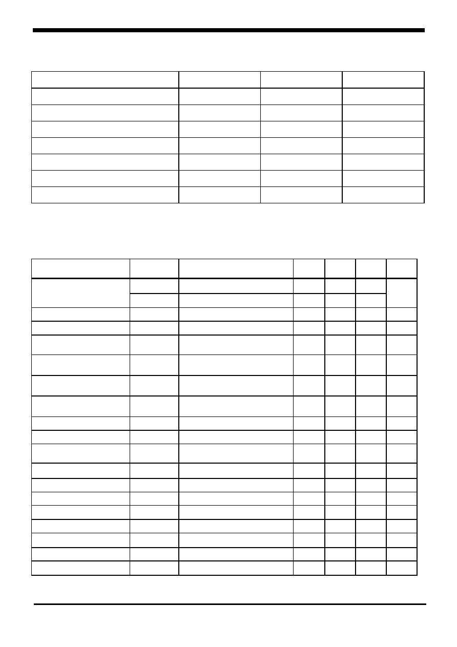
PIN Configuration
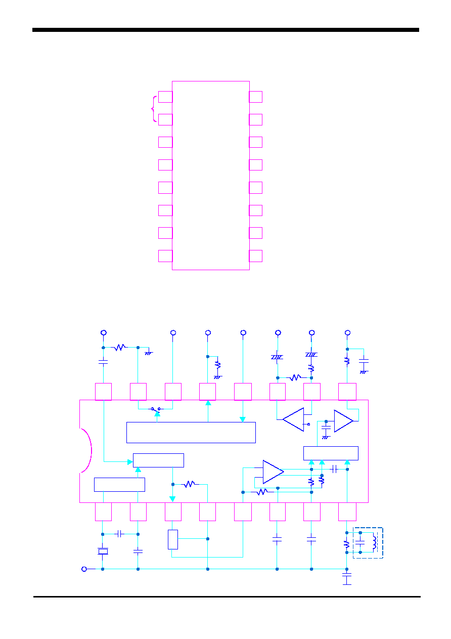
Block Diagram and Test Circuit
SL5018/P
16
15
14
13
12
11
10
9
1
2
3
4
5
6
7
8
-
-
-
-
+
+
+
+
AF
Amp
FL1
FL1
FL1
FL1
V c c
V c c
V c c
V c c
O s i l l a t o r
O s i l l a t o r
O s i l l a t o r
O s i l l a t o r
Mix e r
Mix e r
Mix e r
Mix e r
De mod u la t or
De mod u la t or
De mod u la t or
De mod u la t or
S q u e l c h T r i gg e r w it h
S q u e l c h T r i gg e r w it h
S q u e l c h T r i gg e r w it h
S q u e l c h T r i gg e r w it h
Hy s t e r e s i s
Hy s t e r e s i s
Hy s t e r e s i s
Hy s t e r e s i s
Filter
Amp
Limiter
Amp
+
+
+
+
+
+
+
+
51
51
51
51
0.01
0.01
0.01
0.01
10K
10K
10K
10K
S Q S W
S Q S W
S Q S W
S Q S W
in p u t
in p u t
in p u t
in p u t
470K
470K
470K
470K
1.0
1.0
1.0
1.0
1.0
1.0
1.0
1.0
510
510
510
510
8.2k
8.2k
8.2k
8.2k
0.01
0.01
0.01
0.01
1.8K
1.8K
1.8K
1.8K
1.8K
1.8K
1.8K
1.8K
50K
50K
50K
50K
52K
52K
52K
52K
10P
10P
10P
10P
0.1
0.1
0.1
0.1
0.1
0.1
0.1
0.1
0.1
0.1
0.1
0.1
20K
20K
20K
20K
MURA T A
MURA T A
MURA T A
MURA T A
CF U
CF U
CF U
CF U
455D
455D
455D
455D
220p F
220p F
220p F
220p F
68p F
68p F
68p F
68p F
10.245
10.245
10.245
10.245
MHz
MHz
MHz
MHz
Mix e r In pu t
Mix e r In pu t
Mix e r In pu t
Mix e r In pu t
10.7MHz
10.7MHz
10.7MHz
10.7MHz
A u di o
A u di o
A u di o
A u di o
Mu t e
Mu t e
Mu t e
Mu t e
S c a n
S c a n
S c a n
S c a n
Co nt r o l
Co nt r o l
Co nt r o l
Co nt r o l
Fi l t e r
Fi l t e r
Fi l t e r
Fi l t e r
O u t
O u t
O u t
O u t
Fi l t e r
Fi l t e r
Fi l t e r
Fi l t e r
In
In
In
In
A F O u t
A F O u t
A F O u t
A F O u t
16
15
14
13
12
11
10
9
1
2
3
4
5
6
7
8
DBL5018
DBL5018
DBL5018
DBL5018
R F Inp u t
R F Inp u t
R F Inp u t
R F Inp u t
GND
GND
GND
GND
A u d i o Mu t e
A u d i o Mu t e
A u d i o Mu t e
A u d i o Mu t e
S c a n Co nt r o l
S c a n Co nt r o l
S c a n Co nt r o l
S c a n Co nt r o l
S qu e l c h In pu t
S qu e l c h In pu t
S qu e l c h In pu t
S qu e l c h In pu t
Fi l t e r O u t p u t
Fi l t e r O u t p u t
Fi l t e r O u t p u t
Fi l t e r O u t p u t
Fi l t e r Inp u t
Fi l t e r Inp u t
Fi l t e r Inp u t
Fi l t e r Inp u t
A u d i o O u t pu t
A u d i o O u t pu t
A u d i o O u t pu t
A u d i o O u t pu t
Q u a dr a t u r e Inp u t
Q u a dr a t u r e Inp u t
Q u a dr a t u r e Inp u t
Q u a dr a t u r e Inp u t
De c ou pl i ng
De c ou pl i ng
De c ou pl i ng
De c ou pl i ng
De c ou pl i ng
De c ou pl i ng
De c ou pl i ng
De c ou pl i ng
Li mi t e r Inp u t
Li mi t e r Inp u t
Li mi t e r Inp u t
Li mi t e r Inp u t
V CC
V CC
V CC
V CC
Mi x e r O u t p u t
Mi x e r O u t p u t
Mi x e r O u t p u t
Mi x e r O u t p u t
Cr y s t a l
Cr y s t a l
Cr y s t a l
Cr y s t a l
O S C
O S C
O S C
O S C
SL5018
SL5018P
KSI-W004-000
4
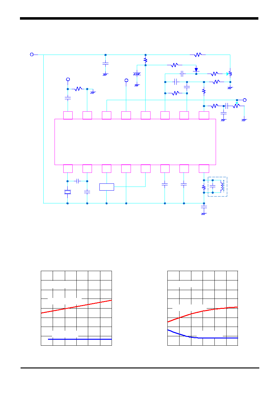
Application Circuit
Typical Performance Characteristics
SL5018/P
16
15
14
13
12
11
10
9
1
2
3
4
5
6
7
8
DBL5018
DBL5018
DBL5018
DBL5018
51
51
51
51
0.01
0.01
0.01
0.01
470K
470K
470K
470K
6.8K
6.8K
6.8K
6.8K
0.022
0.022
0.022
0.022
IF In pu t
IF In pu t
IF In pu t
IF In pu t
10.7MHz
10.7MHz
10.7MHz
10.7MHz
S c a n
S c a n
S c a n
S c a n
Con t r ol
Con t r ol
Con t r ol
Con t r ol
t o P LL
t o P LL
t o P LL
t o P LL
F L1
F L1
F L1
F L1
0.1
0.1
0.1
0.1
0.1
0.1
0.1
0.1
0.1
0.1
0.1
0.1
20K
20K
20K
20K
220p F
220p F
220p F
220p F
68pF
68pF
68pF
68pF
10.245
10.245
10.245
10.245
MHz
MHz
MHz
MHz
10
10
10
10
4.7
4.7
4.7
4.7
100K
100K
100K
100K
1K
1K
1K
1K
18K
18K
18K
18K
0.1
0.1
0.1
0.1
0.001
0.001
0.001
0.001
0.001
0.001
0.001
0.001
4.7K
4.7K
4.7K
4.7K
3.3K
3.3K
3.3K
3.3K
10K
10K
10K
10K
3.3K
3.3K
3.3K
3.3K 0.047
0.047
0.047
0.047
22K
22K
22K
22K
A F
A F
A F
A F
O u t p u t
O u t p u t
O u t p u t
O u t p u t
Q u a d Coi l
Q u a d Coi l
Q u a d Coi l
Q u a d Coi l
FL1 muRata Erie North America type CFU455D2 or equivalent
Quadrature Coil Toko America type 7MC 8128Z or equivalent
SL5018
SL5018P
V
CC
=
4V
2.0
2.0
2.0
2.0
4.0
4.0
4.0
4.0
6.0
6.0
6.0
6.0
8.0
8.0
8.0
8.0
110
110
110
110
120
120
120
120
130
130
130
130
140
140
140
140
150
150
150
150
160
160
160
160
170
170
170
170
180
180
180
180
190
190
190
190
A u di o o u t pu t . Di s t o r t i on
A u di o o u t pu t . Di s t o r t i on
A u di o o u t pu t . Di s t o r t i on
A u di o o u t pu t . Di s t o r t i on
1.0
1.0
1.0
1.0
2.0
2.0
2.0
2.0
3.0
3.0
3.0
3.0
4.0
4.0
4.0
4.0
5.0
5.0
5.0
5.0
6.0
6.0
6.0
6.0
7.0
7.0
7.0
7.0
8.0
8.0
8.0
8.0
AUDIO OUTPUT (Vrms)
AUDIO OUTPUT (Vrms)
AUDIO OUTPUT (Vrms)
AUDIO OUTPUT (Vrms)
AUDIO OUTPUT DISTORTION(%)
AUDIO OUTPUT DISTORTION(%)
AUDIO OUTPUT DISTORTION(%)
AUDIO OUTPUT DISTORTION(%)
V c c . S UP P LY V O LT A GE(V d c )
V c c . S UP P LY V O LT A GE(V d c )
V c c . S UP P LY V O LT A GE(V d c )
V c c . S UP P LY V O LT A GE(V d c )
T a = 25
T a = 25
T a = 25
T a = 25
o
o
o
o
C
C
C
C
A u di o O u t p u t
A u di o O u t p u t
A u di o O u t p u t
A u di o O u t p u t
Di s t or t i o n
Di s t or t i o n
Di s t or t i o n
Di s t or t i o n
-40
-40
-40
-40
0
0
0
0
40
40
40
40
80
80
80
80
80
80
80
80
100
100
100
100
120
120
120
120
140
140
140
140
160
160
160
160
180
180
180
180
200
200
200
200
220
220
220
220
240
240
240
240
A u di o o u t pu t . Di s t o r t i on
A u di o o u t pu t . Di s t o r t i on
A u di o o u t pu t . Di s t o r t i on
A u di o o u t pu t . Di s t o r t i on
1.0
1.0
1.0
1.0
2.0
2.0
2.0
2.0
3.0
3.0
3.0
3.0
4.0
4.0
4.0
4.0
5.0
5.0
5.0
5.0
6.0
6.0
6.0
6.0
7.0
7.0
7.0
7.0
8.0
8.0
8.0
8.0
AUDIO OUTPUT (Vrms)
AUDIO OUTPUT (Vrms)
AUDIO OUTPUT (Vrms)
AUDIO OUTPUT (Vrms)
AUDIO OUTPUT DISTORTION(%)
AUDIO OUTPUT DISTORTION(%)
AUDIO OUTPUT DISTORTION(%)
AUDIO OUTPUT DISTORTION(%)
A MBIENT T EMP ER A T UR E(
A MBIENT T EMP ER A T UR E(
A MBIENT T EMP ER A T UR E(
A MBIENT T EMP ER A T UR E(
o
o
o
o
C)
C)
C)
C)
V c c =4.0V
V c c =4.0V
V c c =4.0V
V c c =4.0V
A u di o O u t p u t
A u di o O u t p u t
A u di o O u t p u t
A u di o O u t p u t
Di s t or t i o n
Di s t or t i o n
Di s t or t i o n
Di s t or t i o n
-20
-20
-20
-20
20
20
20
20
60
60
60
60
KSI-W004-000
5
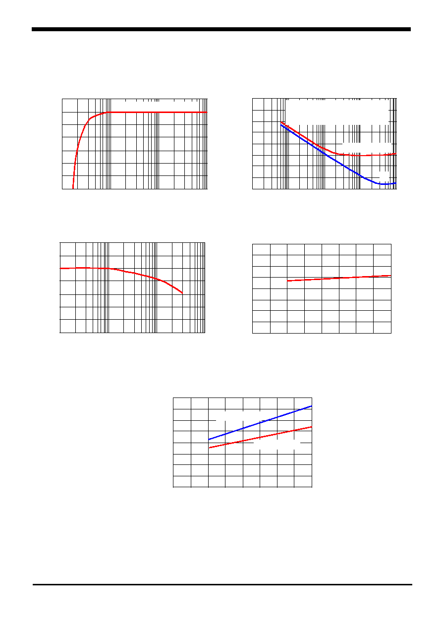
Typical Performance Characteristics (continued)
SL5018/P
0.001
0.001
0.001
0.001
0.01
0.01
0.01
0.01
0.1
0.1
0.1
0.1
1.0
1.0
1.0
1.0
-6.0
-6.0
-6.0
-6.0
-5.0
-5.0
-5.0
-5.0
-4.0
-4.0
-4.0
-4.0
-3.0
-3.0
-3.0
-3.0
-2.0
-2.0
-2.0
-2.0
-1.0
-1.0
-1.0
-1.0
0
0
0
0
1.0
1.0
1.0
1.0
INP UT (mV r ms )
INP UT (mV r ms )
INP UT (mV r ms )
INP UT (mV r ms )
In p u t Li mi t i n g V o l t a g e
In p u t Li mi t i n g V o l t a g e
In p u t Li mi t i n g V o l t a g e
In p u t Li mi t i n g V o l t a g e
A u di o O u t p u t (1.0KHz )
A u d i o O u t pu t (1.0KHz )
A u di o O u t p u t (1.0KHz )
A u d i o O u t pu t (1.0KHz )
LIMITING (dB)
LIMITING (dB)
LIMITING (dB)
LIMITING (dB)
O v e r a l l Ga i n .No i s e . A n d A .M R e j e c t i o n
O v e r a l l Ga i n .No i s e . A n d A .M R e j e c t i o n
O v e r a l l Ga i n .No i s e . A n d A .M R e j e c t i o n
O v e r a l l Ga i n .No i s e . A n d A .M R e j e c t i o n
0.001
0.001
0.001
0.001
0.01
0.01
0.01
0.01
0.1
0.1
0.1
0.1
1.0
1.0
1.0
1.0
10
10
10
10
-60
-60
-60
-60
-50
-50
-50
-50
-40
-40
-40
-40
-30
-30
-30
-30
-20
-20
-20
-20
-10
-10
-10
-10
0
0
0
0
10
10
10
10
-70
-70
-70
-70
INP UT (mV r ms )
INP UT (mV r ms )
INP UT (mV r ms )
INP UT (mV r ms )
RELATIVE OUTPUT (dB)
RELATIVE OUTPUT (dB)
RELATIVE OUTPUT (dB)
RELATIVE OUTPUT (dB)
S +N 3.0KHz F M
S +N 3.0KHz F M
S +N 3.0KHz F M
S +N 3.0KHz F M
V o l t me t e r F r e q u e nc y R a n g e
V o l t me t e r F r e q u e nc y R a n g e
V o l t me t e r F r e q u e nc y R a n g e
V o l t me t e r F r e q u e nc y R a n g e
10 Hz ~ 100KHz
10 Hz ~ 100KHz
10 Hz ~ 100KHz
10 Hz ~ 100KHz
S +N(30% A M)
S +N(30% A M)
S +N(30% A M)
S +N(30% A M)
N
N
N
N
+
+
+
+
-
-
-
-
0
0
0
0
10
10
10
10
20
20
20
20
30
30
30
30
40
40
40
40
50
50
50
50
60
60
60
60
70
70
70
70
GAIN (dB)
GAIN (dB)
GAIN (dB)
GAIN (dB)
80
80
80
80
1.0
1.0
1.0
1.0
2.0
2.0
2.0
2.0
3.0
3.0
3.0
3.0
4.0
4.0
4.0
4.0
5.0
5.0
5.0
5.0
6.0
6.0
6.0
6.0
7.0
7.0
7.0
7.0
8.0
8.0
8.0
8.0
V c c . S UP P LY V O LT A GE (V d c )
V c c . S UP P LY V O LT A GE (V d c )
V c c . S UP P LY V O LT A GE (V d c )
V c c . S UP P LY V O LT A GE (V d c )
F i l t e r A MP Ga i n
F i l t e r A MP Ga i n
F i l t e r A MP Ga i n
F i l t e r A MP Ga i n
0
0
0
0
2
2
2
2
4
4
4
4
6
6
6
6
SUPPLY CURRENT (mAdc)
SUPPLY CURRENT (mAdc)
SUPPLY CURRENT (mAdc)
SUPPLY CURRENT (mAdc)
8
8
8
8
2.0
2.0
2.0
2.0
4.0
4.0
4.0
4.0
6.0
6.0
6.0
6.0
8.0
8.0
8.0
8.0
V c c . S UP P LY V O LT A GE (V d c )
V c c . S UP P LY V O LT A GE (V dc )
V c c . S UP P LY V O LT A GE (V d c )
V c c . S UP P LY V O LT A GE (V dc )
S u pp l y Cu r r e n t
S u p p l y Cu r r e n t
S u pp l y Cu r r e n t
S u p p l y Cu r r e n t
S qu e l c h O n
S qu e l c h O n
S qu e l c h O n
S qu e l c h O n
S q u e l c h O ff
S q u e l c h O ff
S q u e l c h O ff
S q u e l c h O ff
1.0K
1.0K
1.0K
1.0K
10K
10K
10K
10K
100K
100K
100K
100K
1.0M
1.0M
1.0M
1.0M
0
0
0
0
10
10
10
10
20
20
20
20
30
30
30
30
40
40
40
40
50
50
50
50
60
60
60
60
70
70
70
70
F R EQ UENCY (Hz )
F R EQ UENCY (Hz )
F R EQ UENCY (Hz )
F R EQ UENCY (Hz )
F i l t e r A MP R e s p o ns e
F i l t e r A MP R e s p o ns e
F i l t e r A MP R e s p o ns e
F i l t e r A MP R e s p o ns e
GAIN (dB)
GAIN (dB)
GAIN (dB)
GAIN (dB)