 | ÐлекÑÑоннÑй компоненÑ: SPG1316-H | СкаÑаÑÑ:  PDF PDF  ZIP ZIP |
Äîêóìåíòàöèÿ è îïèñàíèÿ www.docs.chipfind.ru
KLG-4002-000
1
SPG1316-H
Chip LED Lamp
Features
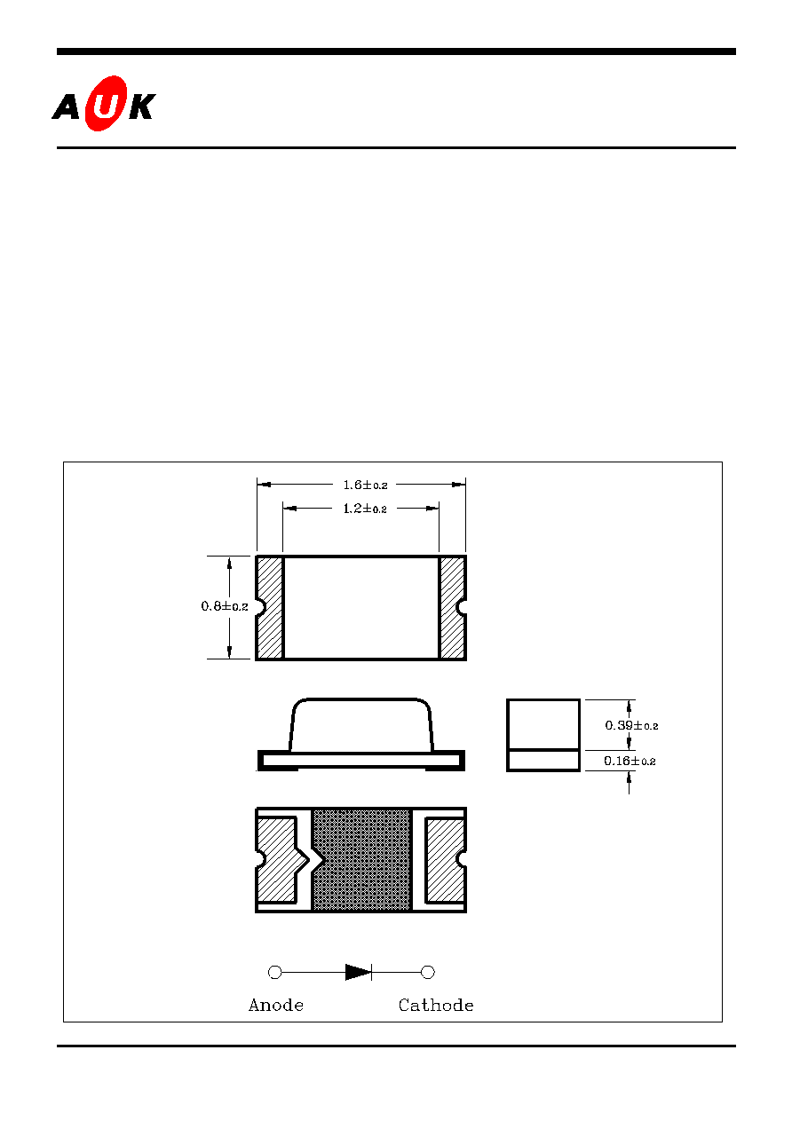
· 1.6mm(L)×0.8mm small size surface mount type
· Thin package of 0.4mm(H) thickness
· Transparent clear lens optic
· Low power consumption type chip LED
· Emitting light green (525nm)
Applications
· LCD backlighting
· Keypad backlighting
· Symbol backlighting
· Front panel indicator lamp
Outline Dimensions unit :
mm
S
S
e
e
m
m
i
i
c
c
o
o
n
n
d
d
u
u
c
c
t
t
o
o
r
r
KLG-4002-000
2
SPG1316-H
Absolute maximum ratings
Characteristic Symbol
Ratings
Unit
Power Dissipation
P
D
80
mW
Forward Current
I
F
20
mA
*
1
Peak Forward Current
I
FP
50
mA
Reverse Voltage
V
R
4
V
Operating Temperature
T
opr
-2580
Storage Temperature
T
stg
-30100
*
2
Soldering Temperature
T
sol
240 for 5 seconds
*1.Duty ratio = 1/16, Pulse width = 0.1ms
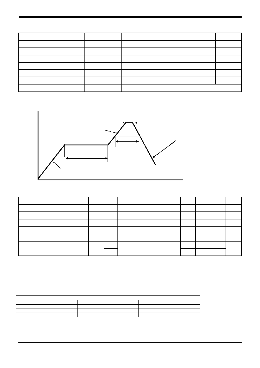
*2. Recommended soldering Temperature Profile
Preheating
area
120
Temp(
)
220
Solder area
max. 50sec
1~ 4/sec
-2~ -6/sec
1~4/sec
Peak time max 10sec
Peak Temp max
240
140~ 160
Time(sec)
Electrical Characteristics
Characteristic Symbol
Test Condition
Min Typ Max Unit
*
3
Forward Voltage
V
F
I
F
= 10mA
2.6
3.0
3.6
V
*
4
Luminous Intensity
I
V
I
F
= 10mA
62
100
228
mcd
Peak Wavelength
P
I
F
= 10mA
-
525
-
nm
Spectrum Bandwidth
I
F
= 10mA
-
35
-
nm
Reverse Current
I
R
V
R
=4V -
-
10
uA
X
-
±65
-
*
5
Half Angle
1/2
Y
I
F
= 10mA
-
±70
-
deg
*3. Forward Voltage Maximum tolerance for ±0.1V
*4. Luminous Intensity Maximum tolerance for each Grade Classification limit is ±18%
(The test result of IF=20mA is only for reference)
*5.
1/2
is the off-axis angle where the luminous intensity is
1/2
the peak intensity
Iv / VF /p Grade Classification
Test Condition @IF=10mA
Forward Voltage(V)
Luminous Intensity(mcd)
Peak Wavelength(nm)
3 : 2.8~3.0
B : 78~105
A : 515~520
4 : 3.0~3.2
C : 105~140
B : 520~525
5 : 3.2~3.4
D : 140~190
C : 525~530
KLG-4002-000
3
SPG1316-H
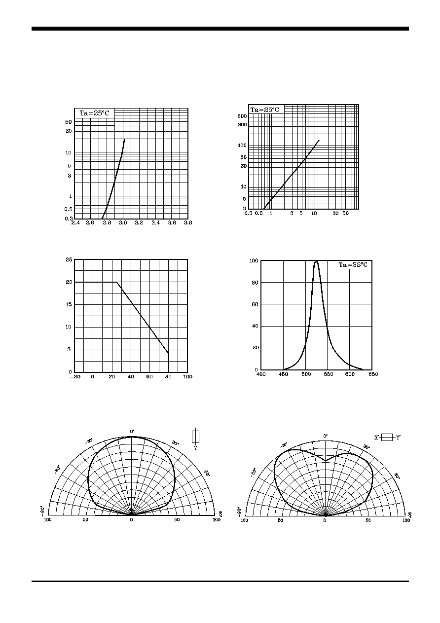
Characteristic Diagrams
Fig.4 Spectrum Distribution
Fig. 3 I
F
Ta
Fig. 2 I
V
- I
F
Fig. 1 I
F
- V
F
F
o
rward Current
I
F
[mA]
Ambient Temperature Ta []
R
e
lative Int
e
nsit
y
[%]
Wavelength [nm]
Forward Voltage V
F
[V]
F
o
rward Current
I
F
[mA]
Forward Current I
F
[mA]
Luminous Intensit
y I
v
[mc
d
]
Fig. 5-1 Radiation Diagram(X)
Relative Luminous Intensity Iv [%]
Fig. 5-2 Radiation Diagram(Y)
Relative Luminous Intensity Iv [%]

KLG-4002-000
4
SPG1316-H
These AUK products are intended for usage in general electronic equipments(Office and
communication equipment, measuring equipment, domestic electrification, etc.).
Please make sure that you consult with us before you use these AUK products in equipm-
ents which require high quality and/or reliability, and in equipments which could have
major impact to the welfare of human life(atomic energy control, airplane, spaceship, traffic
signal, combustion central, all types of safety device, etc.).
AUK cannot accept liability to any damage which may occur in case these AUK products
were used in the mentioned equipments without prior consultation with AUK.