Document No. 422CON4500 - pg. 1/2
© B&B Electronics ≠ Revised November 2000
This product designed and manufactured in USA of domestic and imported parts by
RS-232 To RS-422 Converter
CE
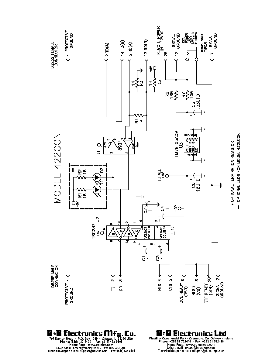
Model 422CON
This RS-232 to RS-422 converter converts unbalanced RS-232 signals to
balanced RS-422 signals. The RS-422 Standard uses a balanced voltage digital
interface to allow communications of 90K bits per second on cable lengths of 4000 feet.
Ten receivers can be connected to any one driver for use in multi-drop systems.
The RS-232 port uses a male DB25 type of connector with pins 2(TD input) and
3(RD output) supported. Protective ground (pin 1) and Signal Ground (pin 7) are also connected. The RS-422 port uses a
female DB-25 type of connector with the Send Data outputs on pins 2 and 14, and the Receive Data inputs on pins 5 and
17. Protective Ground (pin 1) and Signal Ground (pin 7) are connected through to the RS-232 connector.
Interconnection of the converter with another RS-422 device:
1.
The polarity of the two RS-422 lines must be correct. With no data being sent the RS-232 line should be negative
and the RS-422 "A"terminal should be negative with respect to the "B" terminal. If your equipment uses a + and - naming
scheme, in most cases the A line will be connected to the "-", and the B line will be connected to the "+".
2.
The wire recommended in the RS-422 Standard is number 24 AWG copper conductor, twisted-pair telephone
cable with a shunt capacitance of 16 pF per foot.
3.
For long runs and/or high data rates it is recommended that the wires be terminated with a resistor at the receive
end. The twisted pair usually used has an impedance of about 100 ohms, therefore a 100 ohm resistor is normally used
for the termination. The RS-422 side of the converter requires more power as the transmission line is increased and as
the termination resistor value is reduced, therefore it may be necessary to use a termination resistor that is larger than 100
ohms.
4.
The RS-422 driver has the ability to drive 10 RS-422 receivers connected in parallel. A system of multiple
receivers may require some experimentation with location and size of termination resistors, line lengths, grounding, etc.
5.
The RS-422 Standard recommends that Protective Ground (pin 1) be connected to a good "green wire" ground.
This may be already connected in your RS-232 equipment. Protective Ground and Signal Ground should be connected
through to each end of the system and be connected to each other using a 100 ohm 1/2 watt resistor at one end only. If a
shielded twisted pair is used the shield should be connected to Protective Ground.
DECLARATION OF CONFORMITY
Manufacturer's Name:
B&B Electronics Manufacturing Company
Manufacturer's Address:
P.O. Box 1040
707 Dayton Road
Ottawa, IL 61350 USA
Model Numbers:
422CON
Description:
RS-422 Converter
Type:
Light industrial ITE equipment
Application of Council Directive: 89/336/EEC
Standards:
EN 50082-1 (IEC 801-2, IEC 801-3, IEC 801-4)
EN 50081-1 (EN 55022, IEC 1000-4-2)
EN 61000 (-4-2, -4-3, -4-4, -4-5, -4-6, -4-8, -4-11)
ENV 50204
EN 55024
Michael J. Fahrion, Director of Engineering