Document No. 422NOICR4500 - pg. 1/2
© B&B Electronics -- Revised November 2000
This product designed and manufactured in USA of domestic and imported parts by
RS-232 to RS-422 Optically Isolated Converter
CE
CE
CE
CE
Model 422NOICR
The RS-232 to RS-422 converter converts unbalanced RS-232 signals to balanced RS-422 signals.
The RS-422 Standard uses a balanced voltage digital interface to allow communications of 90k bits per
second on cable lengths of 4000 feet. Ten receivers can be connected to any one driver for use in multi-
drop systems.
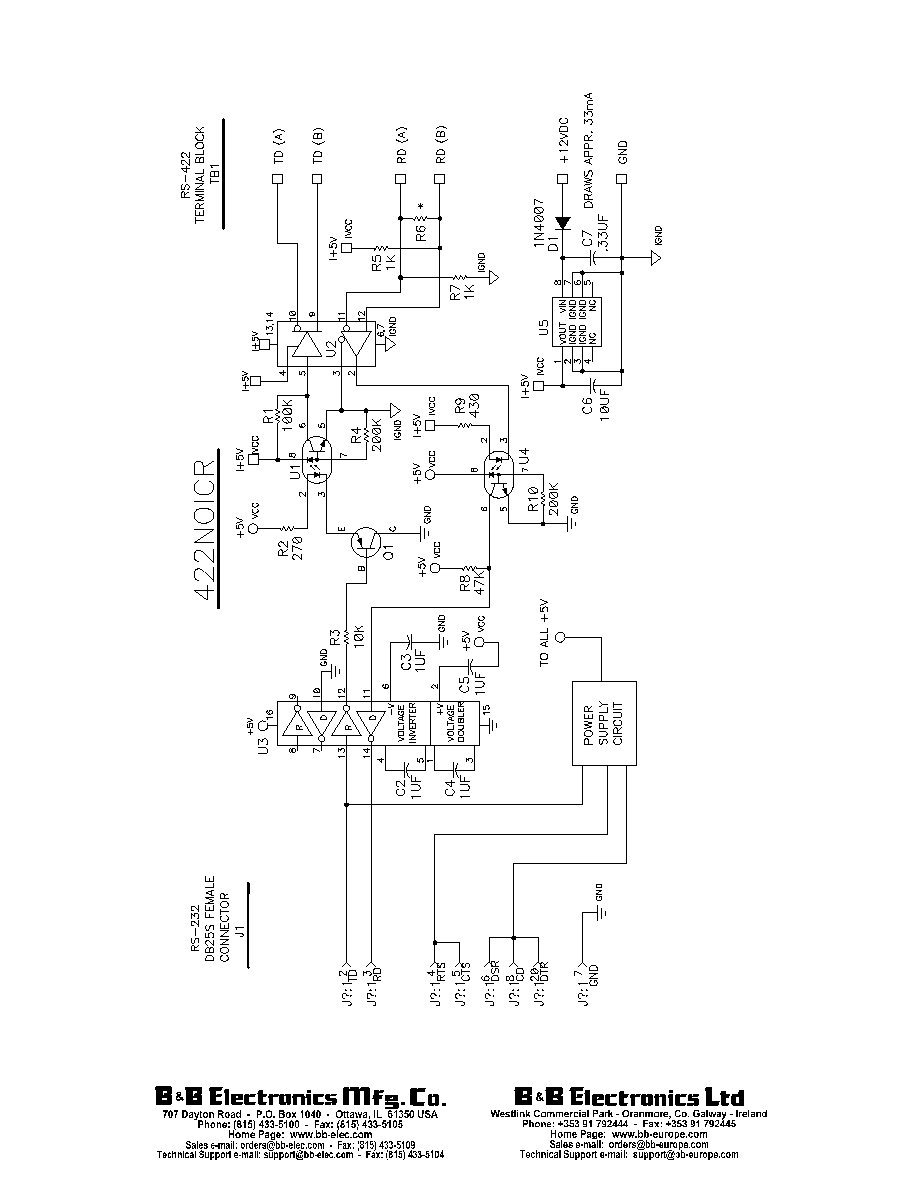
The RS-232 port uses a female DB-25 type of connector with pins 2 (TD input) and 3 (RD output) supported. Protective Ground (pin
1) and Signal Ground (pin 7) are connected on the RS-232 side of the converter. Neither of these two grounds is connected through to the
RS-422 side of the converter. The isolated RS-422 side of the converter has terminal blocks to connect to the user's cables. The terminals
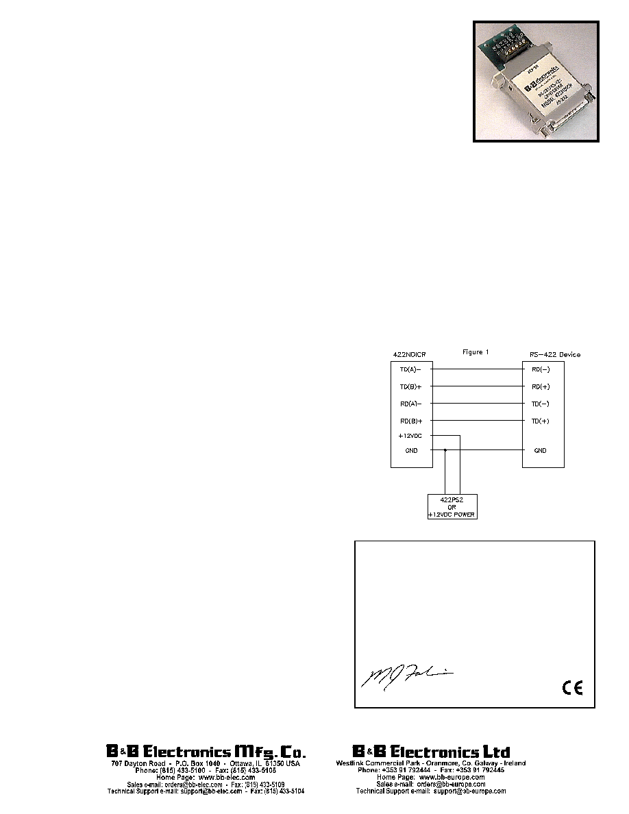
marked "TD (A)" and "TD (B)" are the RS-422 output. The terminals marked "RD (A)" and "RD (B)" are the RS-422 input. Figure 1 shows a
typical connection to an RS-422 device. Twelve (12) VDC power for the RS-422 side of the converter is connected to two more terminal
blocks on the RS-422 side of the converter. These terminals are marked "+12VDC" and "GND".
Interconnection of the converter with another RS-422 device:
1.
The polarity of the two RS-422 lines must be correct. With no data being sent, the RS-232 line should be negative and the RS-422 "A"
terminal should be negative with respect to the "B" terminal.
2.
The wire recommended in the RS-422 Standard is number 24 AWG copper conductor, twisted-pair telephone cable with a shunt
capacitance of 16pF per foot.
3.
For long runs and/or high data rates, it is recommended that the wires be terminated with a resistor at the receive end. The twisted
pair usually has an impedance of about 100 ohms, therefore a 100 ohm resistor is normally used for the termination. In no case
should the termination resistor be less than 90 ohms.
4.
The RS-422 driver has the ability to drive 10 RS-422 receivers connected in parallel. A system of multiple receivers may require some
experimentation with location and size of termination resistors, line lengths, grounding, etc.
To make the converter work:
1.
The RS-232 side of the converter derives its power from pins 2 (TD), 4, 5, 6,
8, and 20. This converter has been tested with all the RS-232 power derived
from pin 2, however, it is recommended that at least one additional
handshake line be connected to the converter to provide power for the RS-
232 side of the converter. The voltage level that exists on the handshake line
does not matter. The converter will be able to derive power from the lines
either in the positive or negative voltage state.
NOTE: When using an external supply, the supply should be connected only
to specifically labeled power inputs (power jack, terminal block, etc.).
Connecting an external power supply to the handshake lines may damage
the unit. Contact technical support for more information on connecting an
external power supply to the handshake lines.
2.
The RS-422 side of the converter must be connected to a 12VDC 100 mA
power supply. Two terminals blocks are provided on the RS-422 side of the
converter to make this connection. These terminal blocks are marked to
make the connection with the proper polarity. To insure proper isolation,
the "GND" terminal on the RS-422 side must not be connected to the
Signal Ground (pin 7) on the RS-232 side of the converter.
Specifications
Data Rate:
Up to 19.2K
Connectors
RS-232 Side:
DB-25 Female (DCE)
RS-422 Side:
Terminal Block
Isolation:
1500V optical isolation of data signals and ground
Power Requirements:
12VDC @ 100 ma.
DECLARATION OF CONFORMITY
Manufacturer's Name:
B&B Electronics Manufacturing Company
Manufacturer's Address:
P.O. Box 1040
707 Dayton Road
Ottawa, IL 61350 USA
Model Numbers:
485DRC and 485LDRC
Description:
RS-485 Optically Isolated Din Mount Converter
Type:
Light industrial ITE equipment
Application of Council Directive: 89/336/EEC
Standards:
EN 50082-1 (IEC 801-2, IEC 801-3, IEC 801-4)
EN 50081-1 (EN 55022, IEC 1000-4-2)
EN 61000 (-4-2, -4-3, -4-4, -4-5, -4-6, -4-8, -4-11)
ENV 50204
EN 55024
Michael J. Fahrion, Director of Engineering