Document No. 422OPINB4898 - pg. 1/2
© B&B Electronics ≠ December 1998
This product designed and manufactured in USA of domestic and imported parts by
Optically Isolated RS-232 to RS-422/485
Model 422OPINB
Description:
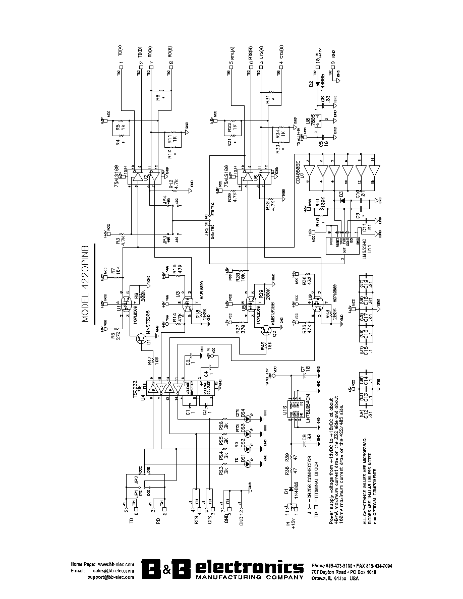
The 422OPINB converts unbalanced, full-duplex RS-232 signals to
balanced, full or half-duplex RS-422 or RS-485 signals. The following signals
are supported: TD on pin 2, RD on pin 3, RTS on pin 4, and CTS on pin 5.
TD & RD can be configured as DTE or DCE with jumpers JP1 & JP2.
Specifications:
Signals Supported:
TD, RD, RTS, & CTS
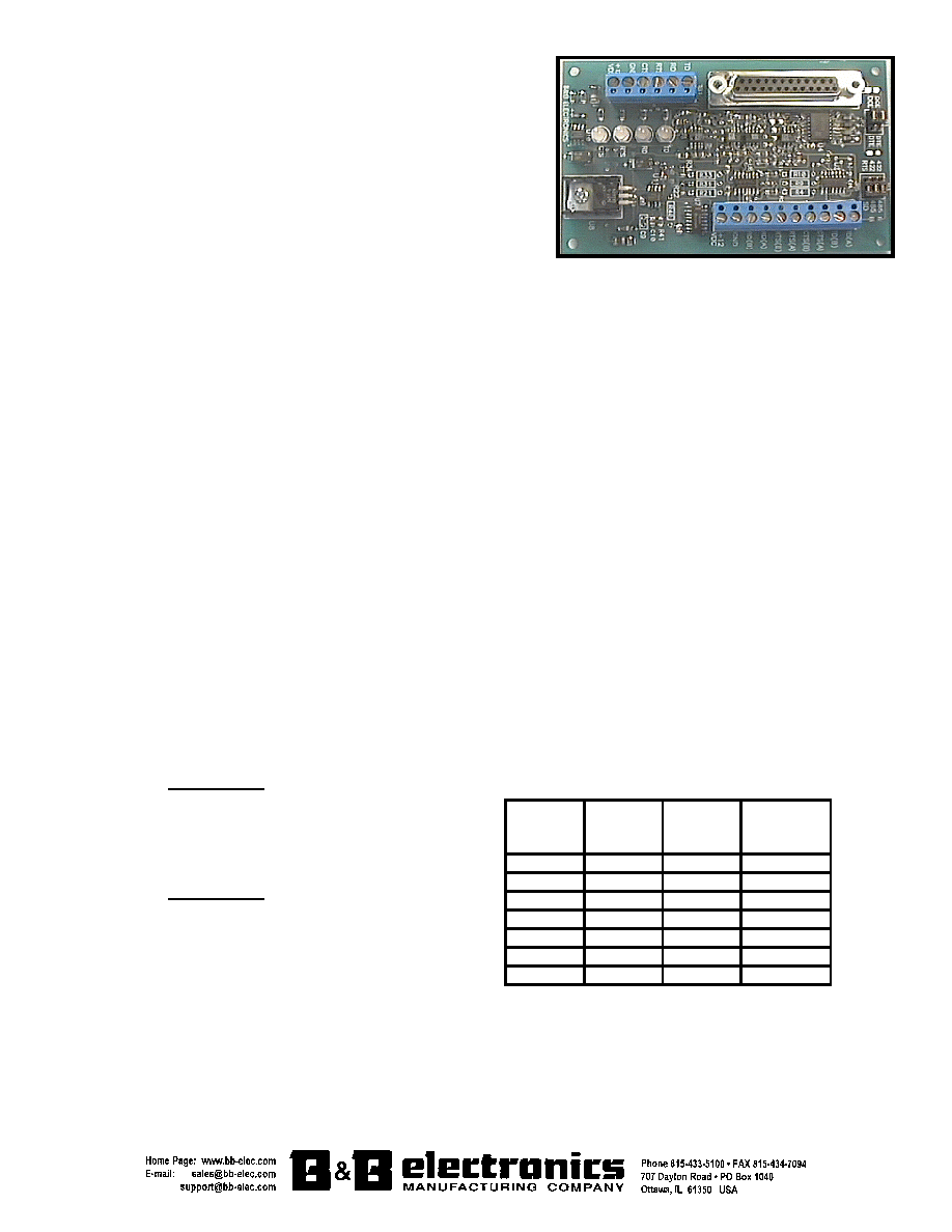
Dimensions:
Approximately 2.75" x 4.60" x 0.68"
Data Rate:
Up to 19.2K baud
Connectors:
RS-232:
DB25S (female) and Terminal Blocks
RS-422/485:
Terminal Blocks
Isolation:
2500VAC optical isolation of data signals and ground
Power Requirements:
RS-232 Side:
From +12VDC to +18VDC at 40mA maximum. Apply to TB1 at +12VDC and GND.
RS-422/485 Side:
From +12VDC to +18VDC at 160mA maximum. Apply to TB2 at I+12VDC and IGND.
Configuration:
In RS-485 mode, the driver enable can either be controlled with the RTS line from the RS-232 port or with an automatic circuit
triggered by the transmission of data. We refer to these as RTS control and SD (send data) control. They are jumper selectable with
jumper JP5. In order for jumper JP5 to have any effect, jumper JP3 must be in the 485 position. When jumper JP4 is in the 485
position, the receiver will be disabled during the transmit of data. The other option is to put jumper JP4 in the 422 position enabling
the receiver all the time. In RTS mode, the RS-485 driver is enabled when the RTS handshaking line is asserted by your software.
You must then disassert RTS in order to turn the RS-485 driver off again. In SD mode, the RS-485 driver is enabled whenever data is
transmitted on the RS-232 TD line and disabled approximately one character length after the end of transmission (factory default is
set for 9600 baud). If time-out errors occur, the baud rate time-out may need adjustment using the component values in Table 1.
R40 & R41 are in parallel with each other. C9 & C10 are also in parallel. If the value of R41 or C9 changes from the factory default,
you must remove that component from the board before adding R40 or C10.
In RS-422 mode, jumpers JP3 & JP4 should be in the 422 position and JP5 has no effect. In 422 mode the driver and receiver
will always be enable for full-duplex communications.
There are 4 two-color LEDs for monitoring the supported signals (red = neg. voltage, green = pos. voltage).
The board layout has an option for termination resistors (approx. 120 ohm): R9 for the 422/485 RD lines, and R31 for the 422
CTS lines.
The RS-422 Standard recommends 24AWG copper conductor, twisted-pair telephone cable with a shunt capacitance of 16pf per
foot up to 4000 feet.
The 232 and 485 power sources must be isolated in order to keep the optical isolation. Power for the 232 side will be connected
to TB1 at +12VDC and GND. The 485 power connects to TB2 at I+12VDC and IGND.
Connect the 422/485 signals to TB2 as follows:
2-WIRE MODE
Table 1. Baud Rate Time-out Replacement Values.
422OPINB: 485 Device:
TD(A) & RD(A) ----------- (A) or (-)
TD(B) & RD(B) ----------- (B) or (+)
If used: RTS(A) & CTS(A) ------- (A) or (-)
RTS(B) & CTS(B) -------- (B) or (+)
4-WIRE MODE
422OPINB: 422/485 Device:
TD(A) -------- Receive Data (A) or (-)
TD(B) -------- Receive Data (B) or (+)
RD(A) --------Transmit Data (A) or (-)
RD(B) -------- Transmit Data (B) or (+)
If used: RTS(A) ------ Clear To Send (A) or (-)
RTS(B) ------ Clear To Send (B) or (+)
CTS(A) ------ Request To Send (A) or (-)
CTS(B) ------ Request To Send (B) or (+)
Baud
Rate
Time
(ms)
Resistor
(
)
R40
Capacitor
(
µ
µ
Fd)
C9
300
33.3
330K
.1
600
16.6
160K
.1
1200
8.33
820K
.01
2400
4.16
430K
.01
4800
2.08
200K
.01
9600
1.04
100K
.01
19200
.520
56K
.01