485DSS3298 - pg. 1/2
© B&B Electronics -- August 1998
Distributed Smart Switch
Model 485DSS
Description
The 485DSS allows non-addressable, "dumb" RS-232 devices to be
connected on an addressable RS-485 network. The master node controls all
communications to connected devices. By distributing the switching
intelligence along the RS-485 network, wiring cost savings are substantial
compared to a single switched "star" configuration. Devices can either be
polled by the master node or request access to the bus through a RS-232 handshake line. This provides a versatile system for
interconnecting devices that are designed for point to point communications. Because the units communicate using standard RS-485
signals, RS-232 devices can form their own network or be added to an existing system. Up to 32 nodes at up to 4000 feet can be on
one bus without a repeater, and the 485DSS's addressing scheme allows up to 256 units on a single network with repeaters.
RS-485 2-Wire or RS-422 4-Wire
Address=1
Address=2
Address=3
RS-232
DEVICE
RS-232
DEVICE
RS-232
DEVICE
HOST
485DSS
485DSS
485DSS
Figure 1. Example of a RS-485 Multi-Node Network
General Operation
On the 485DSS there are three red LED indicators. The LED labeled TD flashes when the RS-232 device is transmitting data.
The LED labeled RD flashes when data is being received from the network. The LED labeled SEL turns on the connection from the
RS-485 port to the RS-232 port is activated. Terminal blocks on the 485DSS connect the RS-485 signals and input power to the unit.
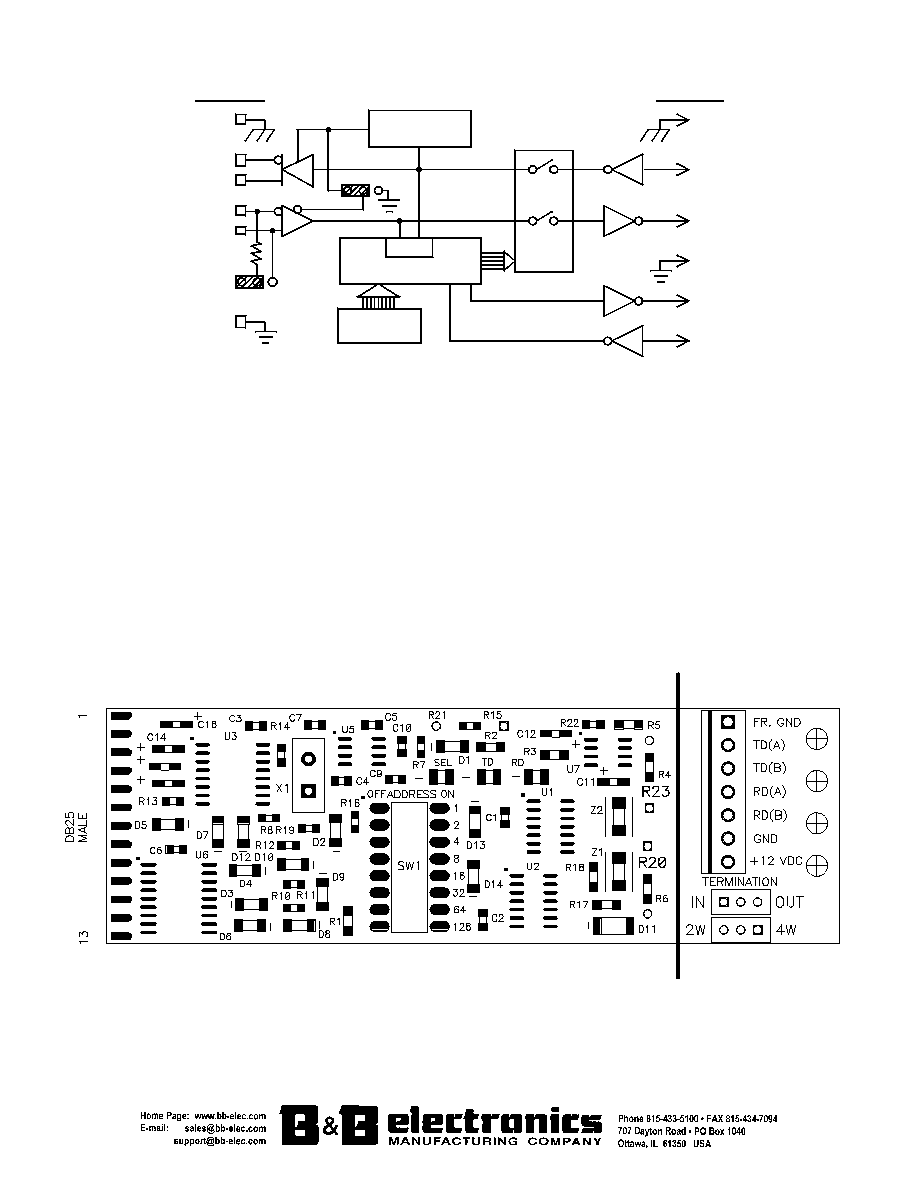
The RS-232 signals of the 485DSS connect to a DB-25 male connector as a DTE device. An eight-position switch (SW1) inside of the
485DSS sets the address. Refer to Figure 3. There are 2 sets of jumpers near the terminal blocks. One set is for 2-wire/4-wire mode
and the other set is for having a 120-ohm termination resistor in line.
The Host computer of the RS-485 network controls each 485DSS on the network by sending them 3 simple control commands.
They allow the host to, turn on (connect) a specified 485DSS to the network, turn off (disconnect) all 485DSS's from the network, and
request status from an individual or from all of the 485DSS's on the network. Each command consists of four ASCII characters: a start
of message character (X-off), two ASCII-HEX address characters or two broadcast characters (DC2), and the command character.
The 485DSS will receive all commands transmitted by the Host. Only one node at a time can access the Host.
Execution of the ON command (SOH character) by the 485DSS asserts the RTS output signal on the RS-232 port and connects
the RS-232 device to the RS-485 network. This command must have a specific address in the address field. Any 485DSS whose
address does not match the command address, will turn off (disconnect) its RS-232 port from the network.
The OFF (EOT character) command disconnects the RS-232 device from the network and lowers the RTS output line. This
command uses only broadcast characters in the address field.
The REQUEST STATUS command (ACK character) allows the Host the ability to prioritize the units on the network based on the
status reply message returned by each 485DSS. The command can also determine if any RS-232 device is requesting access by
monitoring the CTS status of the RS-232 port. This command has two different formats. The first format must contain a specific
address in the address field. The second uses two broadcast characters in the address field. A specific address will return a single
reply. In the broadcast format, all 485DSS's on the network will reply at a predetermined time. The unit's address determines the time
the unit replies. The reply consists of six ASCII characters. An acknowledge character (upper case A), two address characters (in
ASCII-HEX) indicating the address of the unit responding, whether or not the unit has access to the network (0 or 1), the state of the
RS-232 device's CTS handshake line (0 or 1), and a carriage return. Refer to Figure 2.

485DSS3298 - pg. 2/2
© B&B Electronics -- August 1998
4W
2W
TD(B)(+)
Termination
GND
OFF
ON
RD(B)(+)
RD(A)(-)
Microcontroller
Address
Switch
UART
RS-485 Port
FR
GND
TD(A)(-)
Send Data
Control
RD
3
CTS
5
RTS
4
2 TD
7
Switch
Control
RS-232 Port
FR
GND
1
Figure 2. Simplified Functional Diagram
Communications
The 485DSS communicates at 9600 baud, 8 data bits, no parity, and 1 stop bit. Once the Host has connected a 485DSS to the
network, the Host can change its communication parameters to match that of the RS-232 device. There is no connection between the
RS-232 port and the RS-485 port at power up. There is no delay or buffering through the 485DSS. ALL data that is sent from the RS-
485 side after "SELECTION" will be passed through to the RS-232 device.
Included are IBM PC or compatible QuickBasic, Turbo Pascal, Borland, and Microsoft C/C++ executable demonstration programs
with source code. This program demonstrates how to communicate with the 485DSS, and how to retrieve the status reply messages.
The 485DSS is shipped with a manual and a 3 1/2" diskette. Power supply Model 485PS2 purchased separately.
Specifications
Model:
485DSS
Power:
+11 to 16 VDC 75ma
RS-232 Connector:
DB-25 Male (DTE configured)
Size:
4.8L" x 2.15"W x 0.9"H
RS-485 Connector:
Terminal Blocks
Power Supply Model: 485PS2
Communications:
9600 baud, 8 data bits, no parity, and 1 stop bit
Figure 3. Top View of PCBD

