Documentation Number 183COR5098 ≠ pg. 1/2
Not Recommended for New Installations.
Please contact Technical Support for more information.
© B&B Electronics - December 1998
This product designed and manufactured in USA of domestic and imported parts by
NMEA0183 to RS-232/RS-422 or RS-485
CE
Model 183COR
Description:
The 183COR converts one NMEA0183 Version one data signal to either RS-232, RS-422, or RS-485 voltage levels. It also
converts one data signal coming from any of the three EIA Specifications to NMEA0183 voltage levels. The unit can be powered
externally by a wide DC voltage range that is brought in on a pair of stripped and tinned wire leads. The RS-232, RS-422, and RS-485
signals are provided on the same DB-25 female connector, and the NMEA0183 signals are provided on a DB-25 male connector.
NMEA0183 is a standard which describes both the electrical characteristics and the software protocol that should be used for
interfacing electronic marine navigational devices. Version one is an older standard, but many devices are still in use that comply with
these specifications. Electrically, this standard is an unbalanced signal similar to RS-232, but with higher current handling capabilities
and optical isolation on the receive line.
RS-232/RS-422/RS-485 Side:
Connector: DB-25 Female
Signals: RS-232 pins configured as a DCE device.
Passes through TD and RD.
RTS and CTS are tied together.
DTR, DSR, and CD are tied together.
RS-422 and RS-485 provided on the same set of pins.
Automatic enable of RS-422/RS-485 driver.
Easily modified for constant enable of 422/485 receiver.
Space provided for optional 422/485 termination.
NMEA0183 Side:
Connector: DB-25 Male
Signals: Passes through TD and RD.
Zero to Eight volt voltage swing on transmitter.
Transmitter capable of sourcing 15mA in active state.
0.5 volts maximum on receiver for idle or marking state.
4 volts minimum on receiver for active or spacing state.
Receiver input impedance is 1.3K ohms.
2000 volts optical isolation on receiver.
Power Requirements:
Dimensions:
Requires 10 to 30 VDC at 100mA.
3.67" X 2.41" X 0.56"
Operation and Connections:
RS-232:
To 25 pin DTE device (computer, pc, terminal, printer) connect pins 2, 3,
and 7 straight through.
To 25 pin DCE device (modem) cross pins 2 and 3 connect pin 7 straight through.
All 25 pins can be connected if you wish to use a standard 25 pin to 25 pin cable to a DTE or null modem cable to a DCE.
DECLARATION OF CONFORMITY
Manufacturer's Name:
B&B Electronics Manufacturing Company
Manufacturer's Address:
P.O. Box 1040
707 Dayton Road
Ottawa, IL 61350 USA
Model Numbers:
18COR
Description:
NMEA0183 to RS-232/422/485 Converter
Type:
Light industrial ITE equipment
Application of Council Directive:
89/336/EEC
Standards:
EN 50082-1 (IEC 801-2, IEC 801-3, IEC 801-4)
EN 50081-1 (EN 55022)
EN 61000 (-4-3, -4-4)
ENV
50204
Paul A. Boeing, Director of Engineering
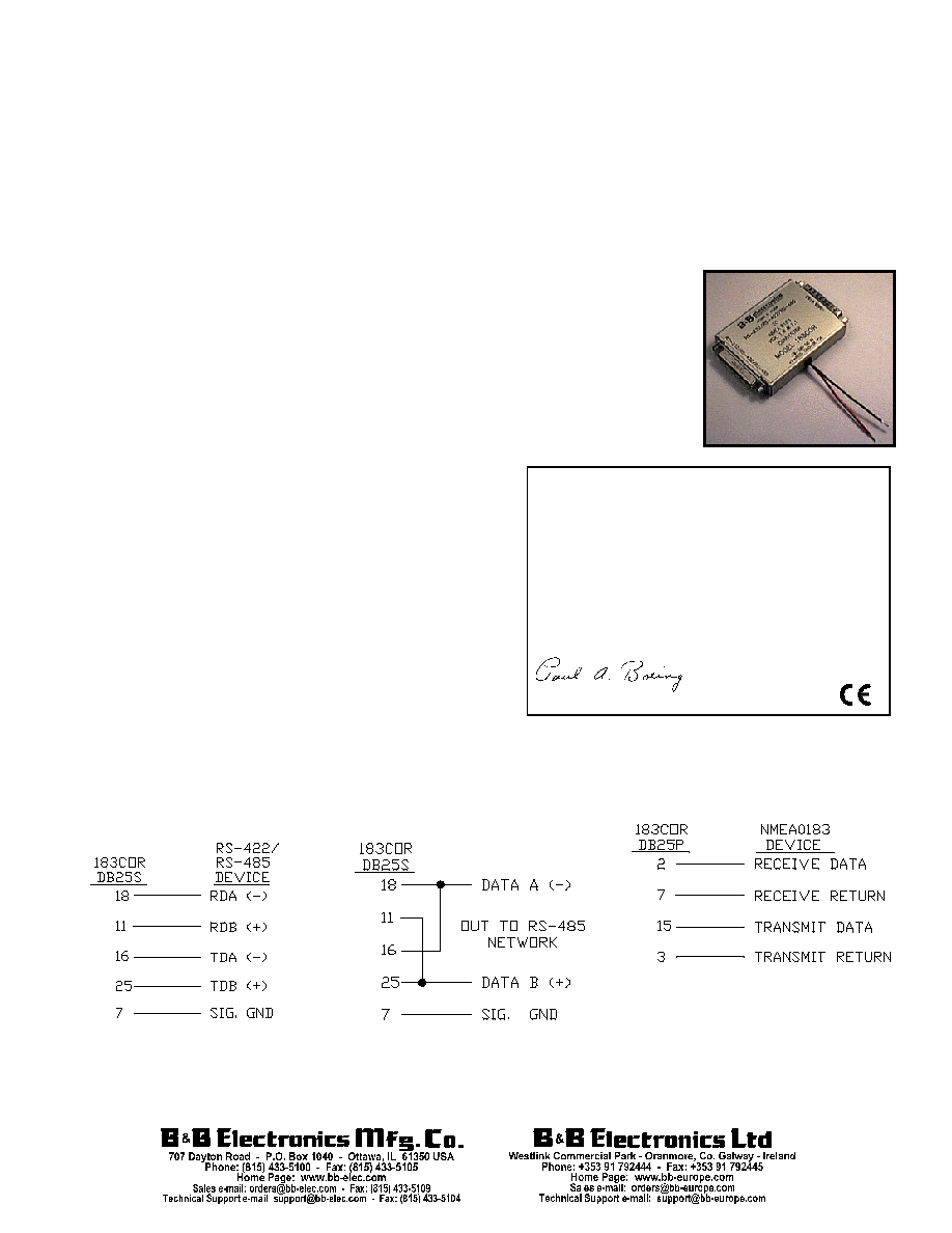
RS-485 two-wire setup:
RS-422 or RS-485 four-wire setup:
NMEA0183 connections:
Documentation Number 183COR5098 ≠ pg. 2/2
Not Recommended for New Installations.
Please contact Technical Support for more information.
© B&B Electronics - December 1998
This product designed and manufactured in USA of domestic and imported parts by
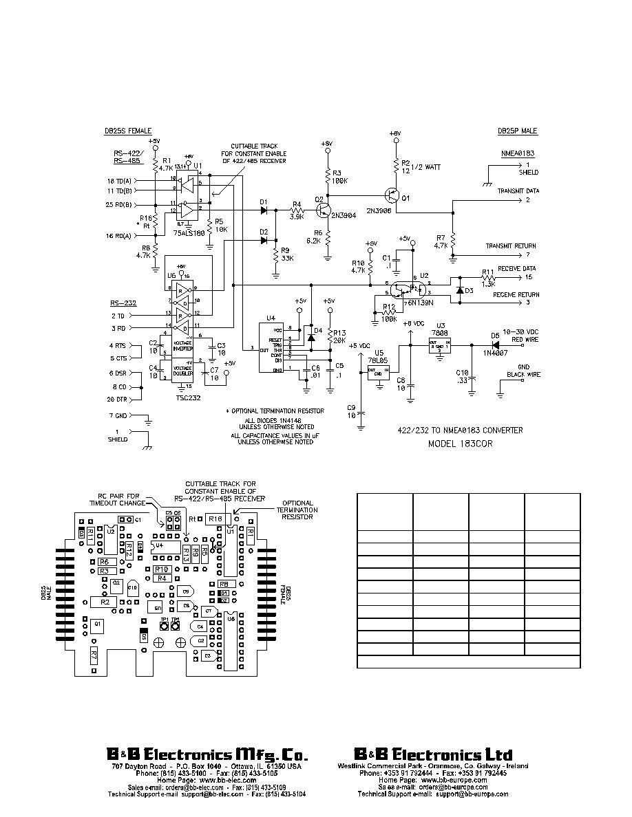
During transmission, the RS-422/RS-485 transmitter is kept enabled for approximately two milliseconds after the transmission
of the last data bit. This is to ensure that no data is cut off at the end of the data stream. This time-out period can be changed by
changing the values of a resistor R13 and capacitor C5 as shown in Table 1.
Space for an optional RS-422/RS-485 termination resistor R16 is provided on the PCBD. This resistor is not normally placed
during manufacturing. If using the 183COR at high data rates or long distances, this space can be used to install a resistor between
the Receive Data A and Receive Data B lines. Normally the value of this termination resistor is 120 ohms to match the approximate
characteristic impedance of the twisted pair wire used. See the RS-422/RS-485 Application Note for more information on termination.
Figure 1.
Figure 2.
Table
1.
Baud
Rate
Time
(ms)
Resistor
R13
(ohm)
Capacitor
C5
(mfd)
300 33.3 33K 1
600 16.6 16K 1
1200 8.33 82K .1
2400 4.16 43K .1
* 4800
2.08
20K
.1
9600 1.04 10K .1
19200 0.520 5.6K
.1
38400 0.260 2.7K
.1
56000 0.176 1.6K
.1
115000 0.0868 8.2K
.01
*
Default Values