
Documentation Number 232CLDR0602 ≠ pg. 1/4
© B&B Electronics -- January 2002
This product designed and manufactured in USA of domestic and imported parts by
DIN Rail Mountable RS-232 to Current Loop
With Terminal Blocks
Model 232CLDR
The 232CLDR is a DIN rail mountable version of B&B's RS-232 to current loop converter.
This unit has one optically isolated 20mA transmit loop and one optically isolated 20mA receive
loop. Each loop can be set to either "Active" or "Passive". When set to "Active" an isolated 20mA
current is supplied for each loop (transmit and receive). Only a single power supply between 10VDC
and 30VDC is required to power the converter and both current loops. Terminal block (A) is RS-232
OUT (from the 232CLDR) and terminal block (D) is RS-232 IN (to the 232CLDR). The 232CLDR
can communicate at a maximum baud rate of 19.2K baud. 20mA current loop is suitable for distances
to 2000 ft. (600 meters) at data rates up to 19.2K baud with careful attention to interface design.
Below are several figures that show different ways to test and configure the 232CLDR.
Documentation Number 232CLDR0602 ≠ pg. 2/4
© B&B Electronics -- January 2002
This product designed and manufactured in USA of domestic and imported parts by
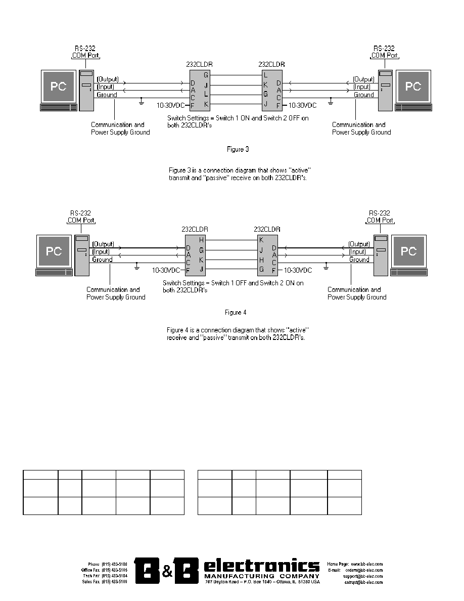
Active or Passive
The 232CLDR can be set to active or passive by the flip of a switch. Figures 1-4 show four different ways to configure the
232CLDR using two PC's. To set SW1 and SW2 you will need to open the hood on the 232CLDR. To open the 232CLDR remove the
side panel by using a flat blade screwdriver. Push the flat blade screwdriver under the panel that has the "MODEL 232CLDR" label
on it and pry the panel off. This panel will simply snap off (and on). The two-position dipswitch is located on the printed circuit board.
Tables 1 and 2 (Transmit and Receive respectively) shown below show connection configurations for active and passive modes.
If you have a separate current loop device (printer, scale, CNC, etc.) you may have to check your device documentation to
see if it is configured as active or passive. If you do not know if your device is active or passive you can simply check it with a
voltmeter. To do this set the voltmeter to DC Volts and put the positive (red) lead on the T+ and the black (negative) lead on the T- of
the current loop device. If you see a voltage displayed on the voltmeter your device is active. If no voltage appears your device is
passive.
Transmit
Receive
SW1 H
G
J SW2 L
K
M
Active
On NC Connect
to R+
Connect
to R-
Active
On NC Connect
to T+
Connect
to T-
Passive
Off Connect
to R+
Connect
to R-
NC
Passive
Off Connect
to T+
Connect
to T-
NC
Table 1
Table 2
Documentation Number 232CLDR0602 ≠ pg. 3/4
© B&B Electronics -- January 2002
This product designed and manufactured in USA of domestic and imported parts by
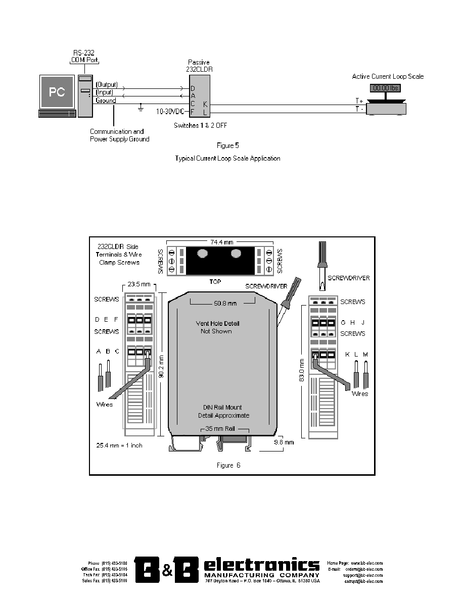
Typical Applications
Figure 5 is a typical application of an "active" current loop scale and the 232CLDR configured in "passive" mode. Some
scale manufacturers sell weight scales that have a current loop interface. A different "active" current loop device of your choice could
easily replace the scale. This figure simply portrays the basic idea of connecting an "active" (Transmit only) current loop device to the
232CLDR (configured as "passive").
Documentation Number 232CLDR0602 ≠ pg. 4/4
© B&B Electronics -- January 2002
This product designed and manufactured in USA of domestic and imported parts by
Specifications:
Dimensions: 3.9 x 2.9 x 0.92 in (100 x 74 x 23mm)
Temperature Range: 0 to 80∞C (32 to 176∞F)
Humidity Range: 0 to 95% Non-condensing
Supply Voltage: +10 to 30VDC @ 100mA
Data Rates: Up to 19.2kbs
Connectors: Screw down terminal blocks for RS-232 and current loop sides
LED's: Two RED data LED's show direction of data flow
Isolation: 1000 VDC isolation for 1 second
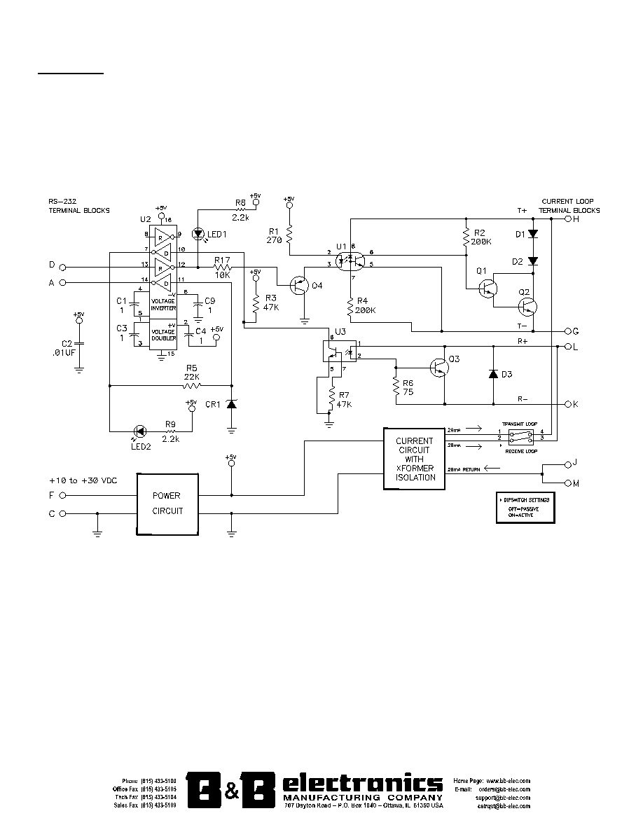
Figure 7. 232CLDR Schematic