232XS53800 Manual
Cover Page
B&B Electronics -- PO Box 1040 -- Ottawa, IL 61350
PH (815) 433-5100 -- FAX (815) 433-5109
Five Port Expandable Smart Switch
Model 232XS5
Document No. 232XS53800
This product designed and manufactured in Ottawa, Illinois USA
of domestic and imported parts by
International Headquarters
B&B Electronics Mfg. Co. Inc.
707 Dayton Road -- P.O. Box 1040 -- Ottawa, IL 61350 USA
Phone 815-433-5100 -- General Fax 815-433-5105
Home Page: www.bb-elec.com
Orders e-mail:
orders@bb-elec.com
-- Fax 815-433-5109
Technical Support e-mail:
support@bb.elec.com
-- Fax 815-433-5104
European Headquarters
B&B Electronics Ltd.
Westlink Commercial Park, Oranmore, Co. Galway, Ireland
Phone: +353 91-92444 -- Fax: +353 91-92445
Internet:
www.bb-europe.com
1997 B&B Electronics -- Revised October 2000

2000 B&B Electronics . No part of this publication may be reproduced or transmitted in any form or by any
means, electronic or mechanical, including photography, recording, or any information storage and retrieval
system without written consent. Information in this manual is subject to change without notice, and does not
represent a commitment on the part of B&B Electronics.
B&B Electronics shall not be liable for incidental or consequential damages resulting from the furnishing,
performance, or use of this manual.
All brand names used in this manual are the registered trademarks of their respective owners. The use of
trademarks or other designations in this publication is for reference purposes only and does not constitute an
endorsement by the trademark holder.

232XS53800 Manual
Table of Contents
i
B&B Electronics -- PO Box 1040 -- Ottawa, IL 61350
PH (815) 433-5100 -- FAX (815) 433-5109
TABLE OF CONTENTS
Chapter 1: INTRODUCTION ................................................... 1
Checklist ..................................................................................... 2
Specifications.............................................................................. 2
Chapter 2: SETUP .................................................................... 3
Port Configuration....................................................................... 4
Serial Data Configuration............................................................ 6
RS-485 Support .......................................................................... 6
Chapter 3: Smart Switch Operation ........................................ 7
Programming the Second Character .......................................... 8
Binary File Transfer .................................................................... 8
Smart Switch/Port Combiner Mode ............................................ 9
Enhanced Timer Mode -- Timer Features ................................ 10
Expansion Mode ....................................................................... 13
Chapter 4: SOFTWARE .......................................................... 15
Introduction ............................................................................... 15
Installation................................................................................. 15
Setup......................................................................................... 15
Default Values .......................................................................... 16
Selecting Ports.......................................................................... 16
Parameters ............................................................................... 16
Appendix A: ASCII Character Codes.................................. A-1
Appendix B: Cable Charts .................................................. B-1
Chart 1. IBM PC DB25 Connector to Master Port ..................B-1
Chart 2. IBM PC DB9 Connector to Master Port ....................B-1
Chart 3. Modem DB25 Connector to Master Port...................B-2
Chart 4. IBM PC DB25 Connector to Ports A - E (DTE) .........B-2
Chart 5. IBM PC DB25 Connector to Ports A - E (DCE).........B-3
Chart 6. IBM PC DB9 Connector to Ports A - E (DTE) ...........B-3
Chart 7. IBM PC DB9 Connector to Ports A - E (DCE)...........B-4
Chart 8. IBM PC DB25 Connector to Ports A - E (DCE).........B-4
Chart 9. IBM PC DB9 Connector to Ports A - E (DCE)...........B-5
232XS2497 Manual
1
B&B Electronics -- PO Box 1040 -- Ottawa, IL 61350
PH (815) 433-5100 -- FAX (815) 433-5109
Chapter 1: INTRODUCTION
The RS-232 Five Port Expandable Smart Switch, Model
232XS5, allows one RS-232 host device to connect to as many as
five RS-232 devices. The switch can be controlled in three different
ways. The first way is referred to as smart switch mode or code
activated switch mode. In this mode, the switch is controlled by
sending a programmable preamble code to the "Master" port of the
232XS5. The second way the switch can be controlled is referred to
as port combiner mode. In port combiner mode, a slave port can
gain access to the master port by asserting a handshake line. If
none of the slave ports have their handshake line asserted, the
switch can be controlled using the preamble code. The third way the
switch can be controlled is the expander mode in which up to four
switches can be cascaded together to form up to 17 slave ports.
The master port can be configured as a DTE or DCE port by an
internal switch setting. If the master port is configured as a DTE
port, the five slave ports will become DCE ports. The 232XS5
supports the following signals: TD, RD, RTS, CTS, DSR, DTR and
DCD.
The 232XS5 has an enhanced timer mode which offers special
timer features. The timer features can be used to prevent slave
devices from receiving preamble commands, inadvertently switching
from binary/graphic file transfers, and inactive slave devices from
holding control of the master port.
The 232XS5 will work with baud rates from 1200 to 115.2K bps;
7 or 8 data bits; even, odd or no parity; and 1 or 2 stop bits (7,N,1 is
not allowed).
NOTE: The data format and rates mentioned are used to switch
the 232XS5. The communication between the devices can use
any format or data rate.

232XS53800
Manual
B&B Electronics -- PO Box 1040 -- Ottawa, IL 61350
PH (815) 433-5100 -- FAX (815) 433-5109
2
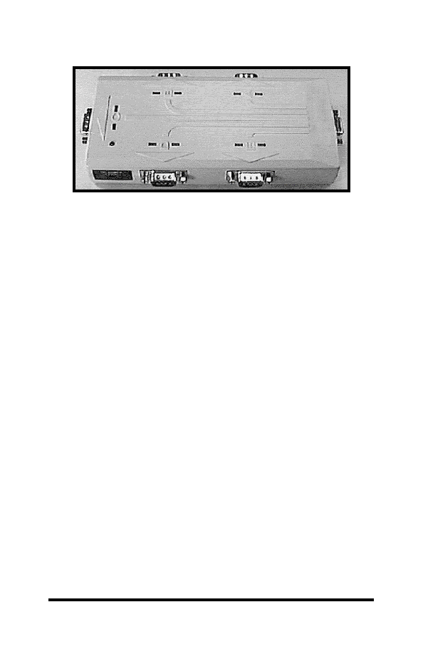
There are five LED's on the 232XS5 to indicate which port is
connected to the master port. The master port has a DB-9S female
connector and the slave ports have DB-9P male connectors. The
232XS5 requires 12Vdc at 100ma. which is provided through a
2.5mm power jack.
Checklist
Examine the shipping carton and contents for physical damage.
If damage is found, file a claim with the shipper immediately.
The following equipment should be in the shipping carton:
1. RS-232 Smart Switch
2. Instruction Manual
3. (1) 3.5" floppy disk
If any of the items above are not in the shipping carton contact
the shipper immediately.
Specifications
Model:
232XS5
Size:
3.0"w x 5.5"l x 1.0"h
Power:
12Vdc to 16Vdc @ 100ma