Documentation Number 485FWTW4698 - pg. 1/2
Not Recommended for New Installations.
Please contact Technical Support for more information.
© B&B Electronics ≠ Revised November 1998
This product designed and manufactured in USA of domestic and imported parts by
Four-Wire RS-422/485 to Two-Wire RS-485 Converter
Model 485FWTW
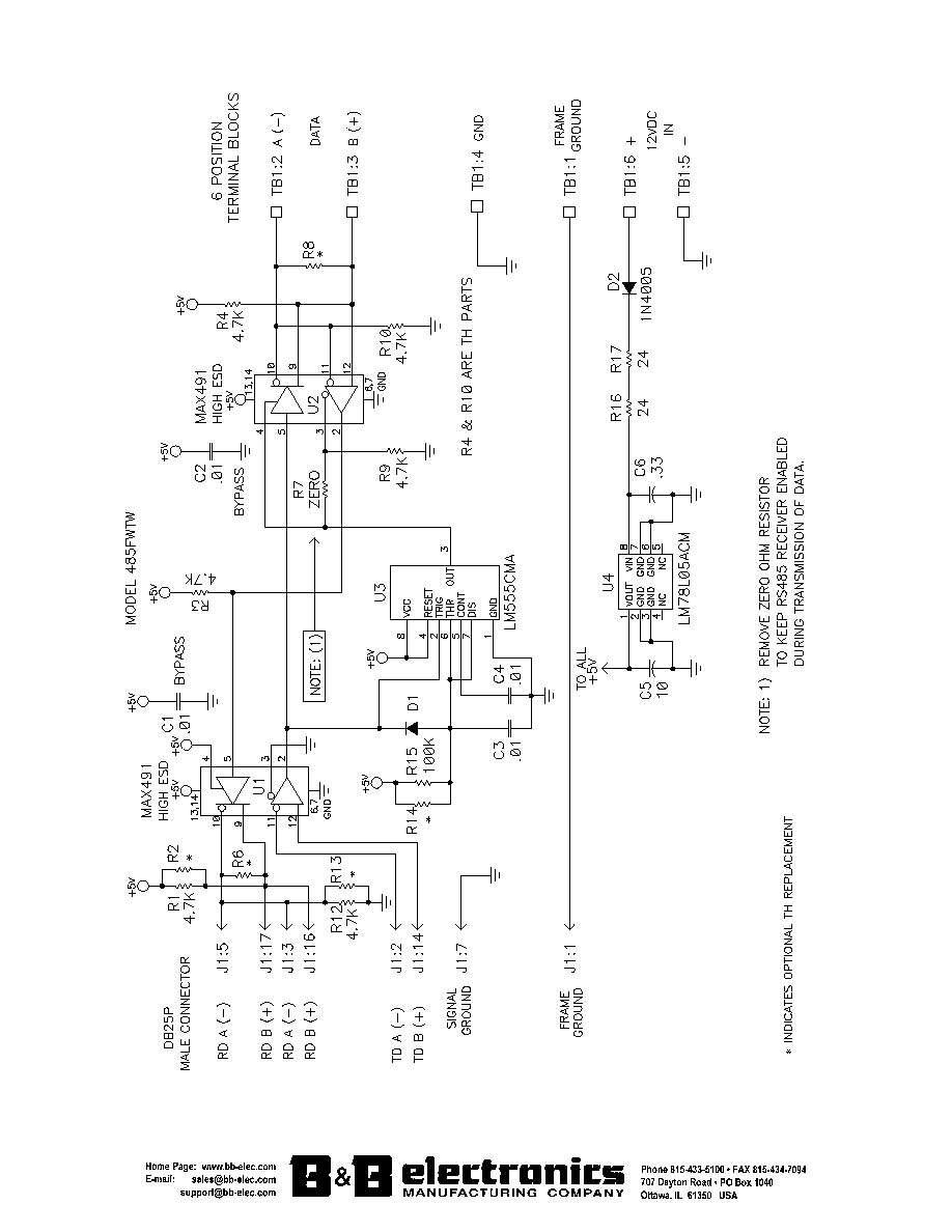
The 485FWTW converts balanced half-duplex RS-422 or RS-485 four-wire signals
(separate TD and RD lines) to two-wire balanced half-duplex signals. RS-485 is an
enhanced version of the RS-422 Balanced Line Standard. It allows multiple drivers and
receivers on a two-wire system.
The four-wire RS-422/RS-485 port uses a male DB25P type of connector with pins
2 (A) and 14 (B) as Transmit Data, and pins 3 or 5 (A) and 16 or 17 (B) as Receive Data.
Protective Ground (pin 1) and Signal Ground (pin 7) are also connected. The two-wire RS-
485 port is a 6-position terminal block with Data A, Data B, Signal Ground, Protective
Ground, and 12 Volt DC power inputs.
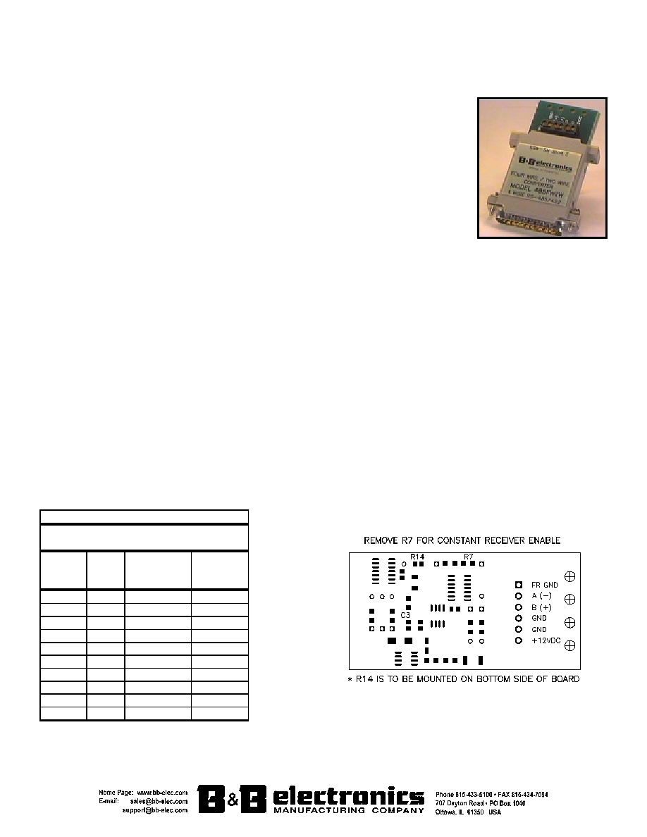
Termination resistors are optional, depending on the line length, baud rate, etc. R8 is the location of an optional
termination resistor. The resistors should be about the impedance of the line used, but in no case should they be less than
120 ohms each. No special software requirements are needed since the RS-485 driver is enabled by the first transition
on the RS-422/RS-485 Transmit Data (pin 2 and pin 14) line. Any transition on the TD line keeps the 485 driver enabled
by preventing the monostable multivibrator from timing out. The transmitter is disabled approximately 1ms after the last
transmitted character. This 1ms timeout allows continuous transmission of data at 9600 baud or higher. R14 and C3 are
the two timeout components. Figure 1 shows where these components are located. Contact B&B Technical Support if you
have questions on changing timeout components. When the converter is transmitting data, the receiver on the two-wire
RS-485 side is disabled. Figure 1 also shows the location of R7, which can be removed to constantly enable the RS-485
receiver.
Up to 32 receivers can be driven by any one generator. This allows you to put together large systems with many
drop points. The termination resistors should be located approximately at the opposite ends of the system.
Proper operation of any RS-485 system requires the presence of a signal return path. The RS-485 Standard
recommends that a third wire be used for this. For safety, a 100 ohm 1/2 watt resistor should be connected between pin 7
and the "reference" wire at every drop point. While it may be possible to interconnect signal grounds (pin 7's) directly, this
is not recommended due to the danger of circulating currents possibly being present.
No wire type or maximum run length is listed in the RS-485 Standard. However, the RS-422 Standard, which is
very similar, recommends number 24 AWG twisted-pair telephone cable with a shunt capacitance of 16 picofarads per
foot and no more than 4000 ft. of distance.
Table 1
COMPONENT REPLACEMENTS FOR
CHANGING BAUD RATE TIMEOUTS
Baud
Rate
Time
(ms)
Resistor
(R14)
(ohm)
Capacitor
(C3)
(mfd)
300 33.3 330K
0.1
600 16.6 160K
0.1
1200 8.33 820K
0.01
2400 4.16 430K
0.01
4800 2.08 200K
0.01
9600 1.04 100K
0.01
19.2K 0.52
56K
0.01
38.4K 0.26
27K
0.01
57.6K 0.176
16K
0.01
115.2K 0.0868
8.2K 0.01
Figure 1
Documentation Number 485FWTW4698 - pg. 2/2
Not Recommended for New Installations.
Please contact Technical Support for more information.
© B&B Electronics ≠ Revised November 1998
This product designed and manufactured in USA of domestic and imported parts by