 | –≠–ª–µ–∫—Ç—Ä–æ–Ω–Ω—ã–π –∫–æ–º–ø–æ–Ω–µ–Ω—Ç: LC25FT | –°–∫–∞—á–∞—Ç—å:  PDF PDF  ZIP ZIP |

Data
sheet
www.bookham.com
Thinking optical solutions
Preliminary
2.5Gb/s Buried Het
8x50GHz Tunable Laser
LC25FT
This laser module employs the Bookham Technology gain
coupled SLMQW buried heterostructure DFB laser chip,
and has been designed specifically for use in Wavelength
Division Multiplexed (WDM) 2.5Gb/s long distance optical
fiber trunk systems.
The device is packaged in a hermetically sealed 14-pin
butterfly package incorporating an isolator and locking
optics to lock and stabilize wavelength and power of the
laser over life.
The module is thermally tunable by means of the internal
thermo-electric cooler over eight adjacent 50GHz ITU
WDM channels.
The device is available with a number of power options
and wavelength schemes that are customised to individual
customer requirements.
www.bookham.com
Thinking optical solutions
Features
∑ 2.5Gb/s Operation
∑ Tunable over eight ITU channels
at 50GHz channel spacing
∑ Integrated wavelength
locking optics
∑ Entire C band ITU wavelengths
available (1528 to 1563nm)
∑ Narrow spectral linewidth
∑ Hermetically sealed 14-pin
butterfly package with
optical isolator
∑ Internal TEC with precision
NTC thermistor
∑ Extended reach performance up to
360km with low dispersion penalty
Applications
∑ Cost effective metropolitan
or long haul networks
∑ Stock inventory / Spares
reduction
∑ Network protection
∑ Low speed routing /
Network Reconfiguration
Preliminary
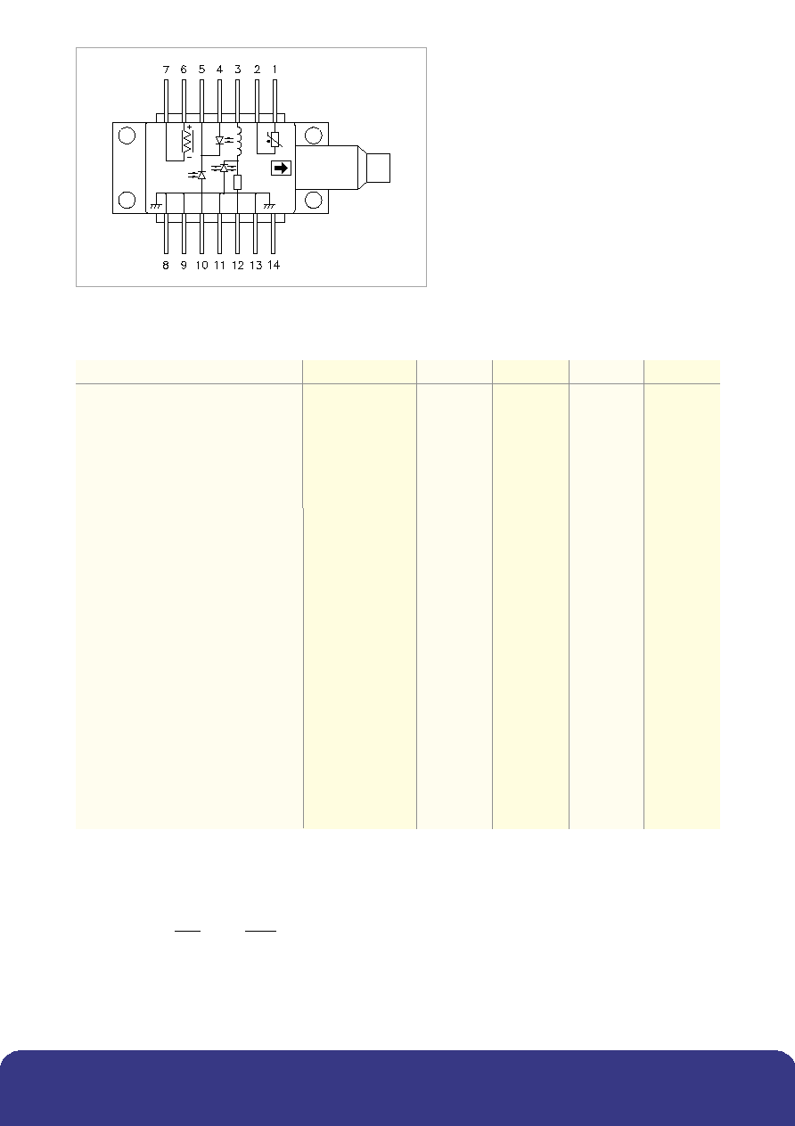
Figure 1: Schematic diagram
www.bookham.com
Thinking optical solutions
www.bookham.com
Thinking optical solutions
(1) 50
measurement system, f = dc ≠ 3GHz
(2) Sub mount temperature between 12.5
∞
C & 47.5
∞
C start of life to achieve required
p
(3) Dispersion penalty is compliant to a link length of 175km or 360km using an extinction ratio of 10dB. Fiber dispersion
characteristics are derived from the following equation.
Where So = 0.092ps/(nm
2
km) and
0
= 1302nm.
(4) Measurements determined from 20 - 80% Pk - Pk
(5) With respect to 25
∞
C case temperature
Characteristics
Parameter
Conditions
Min
Typ
Max
Unit
Threshold current (l
th
)
10
22
mA
Slope efficiency
2mW
0.04
0.09
3mW
0.06
0.13
mW/mA
4mW
0.08
0.17
RF input reflection coef (S
11
)
(1)
-10
dB
Forward voltage
1.3
1.8
V
Peak wavelength (
p
)
(2)
1527
1563
nm
Dispersion penalty
(3)
2
dB
Time averaged spectral linewidth
Modulated. At -20dB
0.4
0.6
nm
SMSR
34
40
dB
Optical rise/fall time
(4)
125
ps
Power monitor current
50
1000
µA
Wavelength monitor current
40
1000
µA
Locked to
p
50
700
µA
Monitor dark current
100
nA
Thermistor resistance
4.25
20.7
k
Heatpump current
T = 60∞C
0.5
1.2
A
Heatpump voltage
T = 60∞C
1.0
2.4
V
Power to wavelength monitor
0.5
1.1
2.5
ratio to achieve
p
Change of
with sub mount temp.
11.5 to 47.5∞C
0.09
nm/∞C
Locked center wavelength accuracy
0 to 70 ∞C
-1.5
+0.8
GHz
case temperature (5)
Total modulated spectral width over
2.5Gb/s modulationEOL
-9 (72)
9 (72)
GHz (pm)
all conditions and life
)
.
/(
)
(
4
)
(
3
4
0
km
nm
ps
So
D
-
=
Reliability/Quality
Meets Qualification requirements of Telcordia GR-468-CORE for central office environment.
Operating reliability <500 FITs
1
in 15 years.
1 - Assumes laser submount is held within the range 9
∞C to 49∞C by the internal thermoelectric cooler
and the product is deployed in equal quantities on each of the eight channels with a mean forward current
of 35mA. End of life limits based on 10mA increase in l
th
and 25% change in laser efficiency. FIT rate data
for other end of life criteria, including minimum extinction ratio requirements, are available upon request.
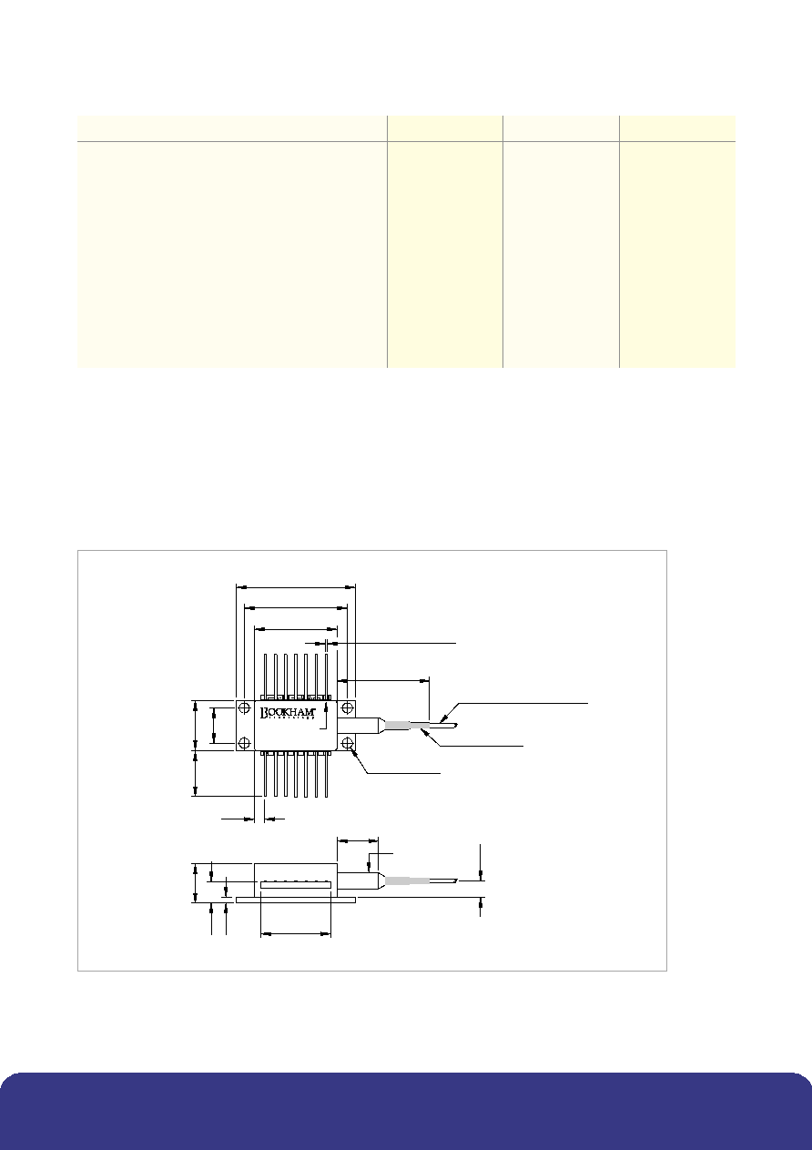
PIN 1
1.5
2
30
26.04±0.08
20.83
14 PINS x 0.5±0.08
8
.
9
12
.
7
1
2
.
7
MIN
2.79
ON 2.54 PITCH
17.8
10.5
ÿ5
9.9
2
4.
12
4 HOLES ÿ2.6
36 MAX
NOSE CONE BOOT
HYTREL SECONDARY COATED
DIMENSIONS IN MILLIMETRES
TOLERANCES UNLESS
OTHERWISE SPECIFIED:
X.XX = ±0.25
X.XXX = ±0.127
MAX
5.
4
6
Figure 2: Outline Drawing and pin out Information
www.bookham.com
Thinking optical solutions
www.bookham.com
Thinking optical solutions
Absolute Maximum Ratings
Parameter
Min
Max
Unit
Case operating temperature
0
+70
∞C
Laser submount operating temperature
9
49
∞C
Storage temperature
-40
85
∞C
Laser current above l
th
100
mA
Laser reverse voltage
1.0
V
Laser reverse current
10
µA
Monitor diode bias
-10
V
Heat Pump Current
1.3
A
Heatpump voltage
2.6
V
Fiber bend radius
30
mm

Instructions for use ≠ LC25FT
Pin 1 and Pin 2 Thermistor
The thermistor is initially used in a control loop in conjunction with the thermo-electric
cooler to maintain the laser submount temperature at the required value. Once the initial
sub-mount temperature is achieved control of the TEC current is handed over to the
etalon locking circuit to achieve fine tuning. Operating current should be less than 100
µA
to prevent self-heating errors.
Pin 3 Laser DC bias (-)
Laser bias current (negative with respect to package ground) is applied via this pin,
which forms one side of the bias-T connection to the laser cathode.
Pin 4 & 10 Monitor anodes, Pin 5 Common Monitor cathode
The output from the wavelength monitor on pin 10 provides the frequency reference,
whilst the power monitor on pin 4 is independent of frequency and a function of laser
output power only. The laser wavelength is matched to a 50GHz ITU grid by adjusting
the ratio of the outputs from pins 4 and 10. Odd and even channels have reversed
locking slopes.
A reverse bias must be applied equally across each of the monitors; applying 5V to pin 5
commonly achieves this.
Pin 6 TEC (+), Pin 7 TEC (-)
Applying a positive voltage on pin 6 with respect to pin 7 will cause the internal sub mount
to be cooled relative to the case temperature. Reversing the polarity will raise the sub mount
temperature relative to the case.
Pin 8, 9, 11, 13 Case ground
These pins must be grounded in all applications.
Pin 12 Laser modulation (-)
The data input (modulation current) is applied via this pin which is a nominal 25
impedance coplanar line. A maximum end of life modulation current of 60mA
should be provisioned.
Pin 14 N/C
This pin is not connected. It should be grounded if possible.
www.bookham.com
Thinking optical solutions
www.bookham.com
Thinking optical solutions
Connections
Pin #
Function
Pin #
Function
1
Thermistor
8
Case ground
2
Thermistor
9
Case ground
3
Laser DC bias (-)
10
Wavelength monitor anode
4
Power monitor anode
11
Laser case ground
5
Both monitor cathodes (+)
12
Laser modulation (-)
6
TEC (+)
13
Laser case ground
7
TEC (-)
14
N/C

Ordering Information
LC25FT [Wavelength]
[Power Option]
[Reach]
[Connector]
****
E = 2mWpk
A = 175km
C28 = SC/PC
C = 3mWpk
B = 360km
C34 = FC/PC
A = 4mWpk
C57 = LC
C59 = MU
Fiber Length 1130 to 1190 mm.
Other connector types are available on request.
**** = Last four digits of first channel / shortest wavelength
E.g. LC25FT4532CA-C28 can be tuned to the following channels:
1545.32nm
1545.72nm
1546.12nm
1546.52nm
1546.92nm
1547.32nm
1547.72nm
1548.12nm
Note that wavelength ranges always start (shortest wavelength)
with a 100GHz channel i.e. LC25FT4572CA-C28 is not an available code,
the next product code after LC25FT4532CA-C28 is LC25FT4612CA-C28
E.g. LC25FT4532AA-C28 is a 4mW 1545.32nm device with an SC/PC connector
for use in a 175km application.
E.g. LC25FT4532CB-C28 is a 3mW 1545.32nm device with an SC/PC connector
for use in a 360 km application.
Lead Trimming option
Devices can be supplied with the leads trimmed to a length of 3.81mm typ.
This option can be specified by adding a `K' suffix after the reach option.
e.g. LC25FT4532AAK-C28 is a 4mW 1545.32 nm to 1547.72nm device with an
SC/PC connector and lead length of 3.81mm (typical) for use in a 175km application.
www.bookham.com
REV 2 August 2003
© Bookham Technology 2003 Bookham is a registered trademark of Bookham Technology plc
North America
Bookham Technology Inc.
49 Buford Highway
Suwanee
GA 30024
USA
∑ Tel: +1 678 482 4021
∑ Fax: +1 678 482 4022
Europe
Bookham Technology plc
Brixham Road
Paignton
Devon
TQ4 7BE
UK
∑ Tel: +44 (0) 1803 66 2875
∑ Fax: +44 (0) 1803 66 2801
Asia
Bookham Technology plc
Hong Kong Representative Office
Rm 2207-9
Tower 2
Lippo Centre
Admiralty, Central
Hong Kong
∑ Tel: +852 2530 8822
∑ Fax: +852 2530 8102
sales@bookham.com
Important Notice
Performance figures, data and any
illustrative material provided in this data
sheet are typical and must be specifically
confirmed in writing by Bookham
Technology before they become applicable
to any particular order or contract.
In accordance with Bookham Technology's
policy of continuous improvement
specifications may change without notice.
The publication of information in this data
sheet does not imply freedom from patent
or other protective rights of Bookham
Technology or others. Further details are
available from any Bookham Technology
sales representative.
TL9000 Rev 3.0 (ISO9001:2000)
FM15040
Site Approvals:
ISO14001:1996
EMS35100