 | –≠–ª–µ–∫—Ç—Ä–æ–Ω–Ω—ã–π –∫–æ–º–ø–æ–Ω–µ–Ω—Ç: LC25T | –°–∫–∞—á–∞—Ç—å:  PDF PDF  ZIP ZIP |
Data
sheet
www.bookham.com
Thinking optical solutions
www.bookham.com
Thinking optical solutions
Features
∑ 2.5 Gb/s Operation
∑ Tunable over four separate
channels at 100 GHz
channel spacing
∑ +/-95pm wavelength stability
over life
∑ Entire C band ITU wavelengths
available (1528 to 1563 nm)
∑ Narrow spectral line-width
∑ Hermetically sealed 14-pin
butterfly package with
optical isolator
∑ Internal TEC with precision
NTC thermistor
∑ Extended reach performance
up to 360 km with low
dispersion penalty
Applications
∑ Cost effective metropolitan
or long haul networks
∑ Stock inventory / Spares
reduction
∑ Network protection
∑ Low-speed routing / Networks
reconfiguration
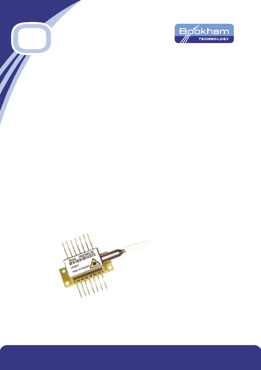
2.5 Gb/s Buried Het
4x100GHz Tunable
Laser with extended
reach option
This laser module employs the Bookham Technology gain
coupled SLMQW buried heterostructure DFB laser chip,
and has been designed specifically for use in Wavelength
Division Multiplexed (WDM) 2.5 Gb/s long distance optical
fibre trunk systems.
The device is packaged in a hermetically sealed 14-pin butterfly
package incorporating an isolator and monitor photodiode
for control of the power of the laser over life and all operating
conditions.
The module is tunable by means of the internal thermo-electric
cooler over four adjacent 100 GHz ITU WDM channels with
a case temperature of 70∞C, or over two adjacent 100 GHZ
channels with a case temperature of 85∞C
The device is available with a number of power options
and wavelength schemes, which are customizable to individual
customer specification.
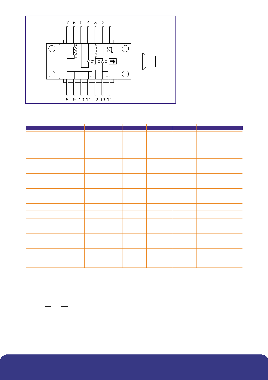
Figure 1: Schematic diagram
Parameter
Conditions
Min
Typ
Max
Unit
Threshold current (Ith)
10
22
mA
Slope efficiency
2 mW
0.04
0.09
mW/mA
3 mW
0.06
0.13
mW/mA
4 mW
0.08
0.17
mW/mA
High Power (1)
0.143
0.43
mW/mA
RF input reflection coef (S11)
(2)
-10
dB
Forward voltage
1.3
1.8
V
Peak wavelength (
p)
(3)
1527
1563
nm
Dispersion penalty
(4)
2
dB
Time averaged spectral linewidth
-20 dB
0.4
0.6
nm
Side-mode suppression
34
40
dB
Optical rise/fall time
(5)
125
ps
Monitor photo current
50
250
1200
µA
Monitor dark current
100
nA
Thermistor resistance
4.07
20.7
k
Heatpump current
T = 64∞C
1000
mA
Heatpump voltage
T = 64∞C
2.4
V
Change of
with laser temp.
8 to 50∞C
0.09
nm/∞C
Change of
over life and
(6)
-45
+145
pm
operating conditions
Parameters
(1) The high power version provides 10 mW peak output power for 175 km applications and 7 mW peak ouput power
for 360 km applications.
(2) 50
measurement system, f = dc - 3 GHz.
(3) Submount temperature between 8∞C & 50∞C start of life to achieve required
p.
(4) Dispersion penalty is compliant to a link length of 175 km or 360 km using an extinction ratio of 10dB. Fibre dispersion
characteristics are derived from the following equation:
where So =0.092 ps/(nm
2
km) and
0
= 1302 nm.
(5) Measurements determined from 20 - 80% Pk - Pk
(6) For more information on wavelength control and drift over life refer to application note DR1670. To give symmetrical
wavelength performance about the ITU channel wavelength (+/-95pm) offset the laser wavelength by ≠50pm at start
of life set up.
)
.
/(
)
(
4
)
(
3
4
0
km
nm
ps
So
D
-
=
www.bookham.com
Thinking optical solutions
www.bookham.com
Thinking optical solutions
Reliability/Quality
Meets Qualification requirements of Telcordia / Bellcore GR468-Core for central office environment.
Operating reliability <500 FITs
1
in 15 years.
1 - Assumes laser die submount is held within the range 8∞C to 50∞C by the internal thermoelectric cooler
and the product is deployed in equal quantities on each of the four channels with a mean forward current of 35 mA.
End of life limits based on 10 mA increase in Ith and 25% change in laser efficiency.
FIT rate data for other end of life criteria, including minimum extinction ratio requirements, are available on request.
Parameter
Min
Max
Unit
Case operating temperature (with 2 x 100 GHz tuning)
-20
85
∞C
Case operating temperature (with 4 x 100 GHz tuning)
-20
70
∞C
Laser submount operating temperature
8
50
∞C
Storage temperature
-40
85
∞C
Laser current above Ith
100
mA
Laser reverse voltage
1.0
V
Laser reverse current
10
µ
A
Monitor diode bias
-10
V
Heat Pump Current
1
A
Heatpump voltage
2.4
V
Fibre bend radius
30
mm
Absolute Maximum Ratings
PIN 1
1.52
30
26.04±0.08
20.83
14 PINS x 0.5±0.08
8.9
12.7
12.7
MIN
2.79
ON 2.54 PITCH
17.8
10.5
ÿ5
9.92
4.12
4 HOLES ÿ2.6
36 MAX
NOSE CONE BOOT
HYTREL SECONDARY COATED
DIMENSIONS IN MILLIMETRES
TOLERANCES UNLESS
OTHERWISE SPECIFIED:
X.XX = ±0.25
X.XXX = ±0.127
MAX
5.46
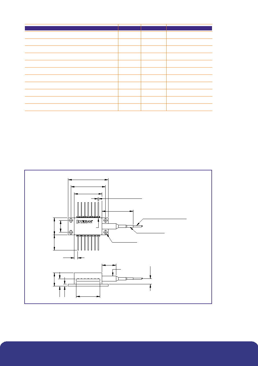
Figure 2: Outline Drawing and Pinout Information
Note: Device can be supplied with the leads trimmed to a length of 3.81 mm typ.
Please see Order Information section.
www.bookham.com
Thinking optical solutions
www.bookham.com
Thinking optical solutions

Pin #
Function
Pin #
Function
1
Thermistor
8
Case ground
2
Thermistor
9
Case ground
3
Laser DC bias (-)
10
N/C
4
Monitor anode (-)
11
Laser case ground
5
Monitor cathode (+)
12
Laser modulation (-)
6
TEC (+)
13
Laser case ground
7
TEC(-)
14
N/C
Connections
Instructions for use ≠ LC25T
Pin 1 and Pin 2 Thermistor
The thermistor is used in a control loop in conjunction with the thermo-electric cooler to maintain
the laser submount temperature at the required value for wavelength. Operating current should
be less than 100 µA to prevent self-heating errors.
Pin 3 Laser DC bias (-)
Laser bias current (negative with respect to package ground) is applied via this pin which forms
one side of the bias-T connection to the laser cathode.
Pin 4 Monitor anode, Pin 5 Monitor cathode
The back facet monitor provides a mean power reference for the laser and is normally operated
with a 5 V reverse bias.
Pin 6 TEC (+), Pin 7 TEC (-)
Applying a positive voltage on pin 6 with respect to pin 7 will cause the internal submount to be
cooled relative to the case temperature. Reversing the polarity will raise the submount temperature
relative to the case. The TEC supply should be capable of delivering up to 0.9 A at 2.4 V.
Pin 8, 9, 11, 13 Case ground
These pins must be grounded in all applications.
Pin 10
This pin is not connected for the LC25T product and it should be grounded if possible.
Pin 12 Laser modulation (-)
The data input (modulation current) is applied via this pin which is a nominal 25 Ohm impedance
coplanar line. For 10mW applications the end of life modulation current is 90mA maximum. For all
other applications 60mA maximum modulation current should be provisioned.
Pin 14 N/C
This pin is not connected. It should be grounded if possible.
www.bookham.com
Thinking optical solutions
www.bookham.com
Thinking optical solutions

Ordering Information
LC25T [Wavelength]
[Power Option]
[Reach]
[Connector]
****
E = 2 mWpk
A = 175 km -
C28 = SC/PC
C = 3 mWpk
B = 360 km -
C34 = FC/PC
A = 4 mWpk
C57 = LC
B = High power
C59 = MU
Fibre Length 1130 to 1190 mm.
Other connector types are available on request.
**** = Last four digits of first channel / shortest wavelength
E.g. LC25T4532CA-C28 has the following four channels:
1545.32 nm
1546.12 nm
1546.92 nm
1547.72 nm
The high power option provides 10 mW peak power at 175 km or 7 mW peak power
over 360 km.
E.g. LC25T4532BA-C28 is a 10 mW 1545.32 to 1547.72 nm device with an
SC connector for use in a 175 km application.
E.g. LC25T4532BB-C28 is a 7 mW 1545.32 to 1547.72 nm device with an
SC connector for use in a 360 km application.
Trimmed lead option
Devices can be supplied with the leads trimmed to a length of 3.81 mm typ.
This option can be specified by adding a `K' suffix after the reach option.
E.g. LC25T4532BBK-C28 is a 7 mW 1545.32 nm device with an SC connector
and a lead length of 3.81mm, for use in a 360 km application.
-20∞C to 85∞C Case Temperature, 2 x 100 GHz Tunable Operation
Where a maximum case temperature of +85∞C is required, the LC25T can be tuned
over 2 adjacent 100 GHz channels.
With the elevated case temperature, the submount temperature tuning range becomes 25∞C to 50∞C.
Parameter
Conditions
Min
Typ
Max
Unit
Thermistor resistance
4.07
10
k
Case operating temperature
-20
85
∞C
Laser submount operating temperature
25
50
∞C
Revised Parameters for 85∞C Case Temperature Operation
www.bookham.com
Thinking optical solutions
www.bookham.com
Thinking optical solutions