Data
sheet
www.bookham.com
Thinking optical solutions
2.5Gb/s InP MZ
Modulator with
DWDM Laser
The 2.5Gb/s InP Mach Zehnder Modulator with DWDM
Laser, containing the Bookham Technology Strained Layer
MQW DFB laser chip and the InP Mach-Zehnder modulator
chip, has been designed specifically for use in 2.5Gb/s long
and very long distance optical fibre trunk systems.
When used with closed loop control, wavelength locking
to the ITU 50GHz grid is achieved.
Due to the negative chirp characteristic, when used on Non
Dispersion Shifted Fibre (NDSF) the module exhibits <1dB
dispersion penalty for 12800ps/nm dispersion. Optical power
control is achieved by applying a D.C. bias voltage to the internal
attenuator electrode. This reduces the power into the modulator
section without affecting the operating wavelength.
www.bookham.com
Thinking optical solutions
Features
∑ Voltage programmable output
power control
∑ Very long haul performance with
negligible penalty
∑ Integral Etalon wavelength
stabilisation to within ± 20pm
over life
∑ Single 50 Ohm low voltage drive
modulation input
∑ Integral thermo-electric cooler
with precision NTC thermistor
for temperature control
∑ Hermetically sealed 14 pin
butterfly package with optical
isolator
∑ ITU Wavelengths available from
1530nm to 1560nm
Applications
∑ Long and very long reach
SONET/SDH OC48/STM16
systems
∑ DWDM systems to 50GHz
channel spacing

Parameter
Conditions
Min
Typ
Max
Unit
Submount temperature
25
35
∞
C
Forward current
250
mA
Modulated output power (1)
50% duty
0.5
4.0
dBm
Modulated output power (2)
at Tcase = 30
∞
C
-12.0
dBm
Case temperature tracking error
Tcase 0 - 70
∞
C
1
dB
Constant wavelength
Aging error
Constant wavelength
0.5
dB
Laser forward voltage
2.75
V
Line width
CW FWHM
2
20
MHz
SMSR
At rated power
40
dB
Modulation voltage
AC pp
1.5
3
V
Drive bias voltage
-3.0
-0.5
V
Fixed arm bias voltage
-3.0
0
V
Extinction ratio
13
dB
RIN
-140
dB/Hz
Locking photo current
0.2
2.0
mA
Monitor dark current
100
nA
Heatpump current
70
∞
C case/25
∞
C chip
1.2
A
RF Return loss S11
0 ≠ 2.5GHz
13
dB
3dB Bandwidth S21
3
GHz
Characteristics
Conditions unless otherwise stated:
Submount temperature
30
∞
C ± 5
∞
C (for locked
)
Monitor diode bias
-5V
Absolute Ratings
Parameter
Conditions
Min
Typ
Max
Unit
Case operating temperature
0
+70
∞
C
Storage Temperature
-40
+85
∞
C
Laser forward current above lth
300
mA
Laser reverse voltage
2
V
Monitor diode bias
-18
V
Fibre bend radius
30
mm
Modulation input
AC + DC bias
6
V
Power tuning pin
Reverse bias
-8
0
V
Power tuning pin
Reverse current
0
27
mA
Note (1) Start of life, power adjustment set for maximum output.
(2) Start of life, power adjustment set to ≠7.3V.
www.bookham.com
Thinking optical solutions
www.bookham.com
Thinking optical solutions
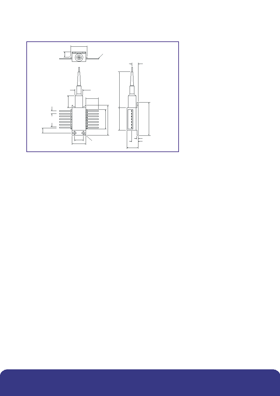
Outline Drawing
Dimensions in mm
Tolerance ± 0.25
Finish: Gold plate
9.8
5.6
5.6
30
20.9
36
1
1
2
3
4
5
6
7
14
0.50
2.54
26.05
17.90
5.16
13.4
13
12
11
10
9
8
12.7
12
9
¯7.1
4 x ¯2.3
4.1
15.2
Pins 0.25 thick
Instructions for Use
Pin 1 and Pin 2 Thermistor
The thermistor is used in the control loop for keeping the
internal temperature at a constant value. It has a nominal
resistance of 8.2 k
at the typical operating temperature
of 30
∞
C and is not polarity sensitive. Operating current
should be limited to less than 100µA to prevent self-heating
errors. The exact thermistor value will be supplied with the
LCM155W variant to ensure correct operating wavelength.
Pin 3 Laser Bias (+) (Anode)
Laser bias current (positive with respect to package
ground) is applied via this pin, which is internally
decoupled to ground. The laser is operated with a
forward bias current up to 250 mA at 2.75 V (typical).
Threshold current is typically 30 mA at 30
∞
C. Laser
cathode is internally connected to case ground.
Pin 4 Monitor Anode (short), Pin 10 Monitor Anode
(long) and Pin 5 Monitor Cathodes
The two back facet monitor diodes are used in a control
loop, which maintains constant laser wavelength. Each diode
has a different spectral response, which overlaps at the
"locked" wavelength. The loop can control submount
temperature and/or laser bias current to maintain the two
monitor diode currents at equal values, corresponding to the
locked wavelength. The diode cathodes are commoned on
pin 5 and are operated with a reverse 5 V bias.
Pin 6 TEC (+) and Pin 7 TEC (-)
Applying a positive voltage on Pin 6 with respect to Pin 7
will cause the internal optics to be cooled relative to the
case temperature. Reversing the applied voltage will
cause the internal structures to be heated. The power
supply for the heatpumps should be capable of sourcing
up to 1.2 A at 5 V.
Pin 8 Power Adjust
A negative DC voltage in the range 0 V to -7.3 V applied to
this pin will attenuate the output power by up to 20 dB.
The supply should be capable of sinking up to 30 mA
from this pin.
Pin 9, 11, 13 Package Ground
Pins 11 and 13 specifically need to be good RF grounds,
since these pin positions are on either side of the RF input.
Pin 12 Data Input
This pin provides both the DC bias to the MZ and the data
input (modulation voltage). The DC bias value and required
modulation voltage are supplied with the device. The DC
bias source is required to deliver about -2.0 V at up to 40
mA and should be connected via an inductor. The
modulation input has characteristic impedance of 50
and should be AC coupled to a suitable driver using 50
tracks. Modulation voltage for optimum extinction ratio is
supplied with the device and may be up to 3.0 Vpp.
Pin 14 MZ Bias
DC bias voltage for the fixed MZ arm. This pin must be
connected to a negative DC voltage (typically around -2.0
V) which is defined in the deliverable data. The bias
voltage source must be capable of delivering up to 10 mA
to this pin.
www.bookham.com
Thinking optical solutions
www.bookham.com
Thinking optical solutions

THIS PRODUCT COMPLIES WITH 21 CFR 1040.10
REFERENCE IEC 60825-1: Edition 1.2
CLASS 1 LASER PRODUCT
DANGER
INVISIBLE LASER RADIATION
AVOID DIRECT
EXPOSURE TO BEAM
OUTPUT POWER 6mW
WAVELENGTH >1520nm
Class 1 for non viewed sources
CAUTION
STATIC SENSITIVE DEVICE
OBSERVE PRECAUTIONS
Certificate No. FM 15040
Certificate No. EMS 35100
Connector types: SC=C28, FC/PC=C33, no suffix=2.5mm o.d ceramic ferrule (Std)
Device Ordering Information
Order Code No. LCM155W**** - 20A (Connector Type)
Where **** = Last four digits of wavelength value i.e for
p = 1545.32nm **** = 4532
For wavelength information see Bookham Technology WDM wavelength plan.
Connector type SC = C28, FC/PC = C33, no suffix = 2.5mm o.d ceramic ferrule (Std)
An Applications Note is also available for this device.
Connections
Pin 1
Thermistor
Pin 14
Bias for fixed MZ arm
2
Thermistor
13
Ground
3
Laser bias (+)
12
Data (DC coupled)
4
BFM Anode short
11
Ground
5
BFM Cathode
10
BFM Anode long
6
Cooler (+)
9
Gound
7
Cooler (-)
8
Power adjust
+
7
6
5
4
3
2
1
8
9
10
11
12
13
14
100n
470n
470n
470n
50
www.bookham.com
REV 1 Feb 2003
© Bookham Technology 2003 Bookham & ASOC are registered trademarks of Bookham Technology plc
North America
Bookham Technology Inc.
49 Buford Highway
Suwanee
GA 30024
USA
∑ Tel: +1 678 482 4021
∑ Fax: +1 678 482 4022
Europe
Bookham Technology plc
Brixham Road
Paignton
Devon
TQ4 7BE
UK
∑ Tel: +44 (0) 1803 66 2875
∑ Fax: +44 (0) 1803 66 2801
Asia
Bookham Technology plc
21/F Cityplaza One
1111 King's Road
Quarry Bay
Hong Kong
∑ Tel: +852 (2100) 2249
∑ Fax: +852 (2100) 2585
Sales@bookham.com
Important Notice
Bookham Technology has a policy of
continuous improvement, as a result
certain parameters detailed on this flyer
may be subject to change without notice.
If you are interested in a particular product
please request the available from any
Bookham Technology sales representative.