*RoHS Directive 2002/95/EC Jan 27 2003 including Annex.
Specifications are subject to change without notice.
Customers should verify actual device performance in their specific applications.
1
2
3
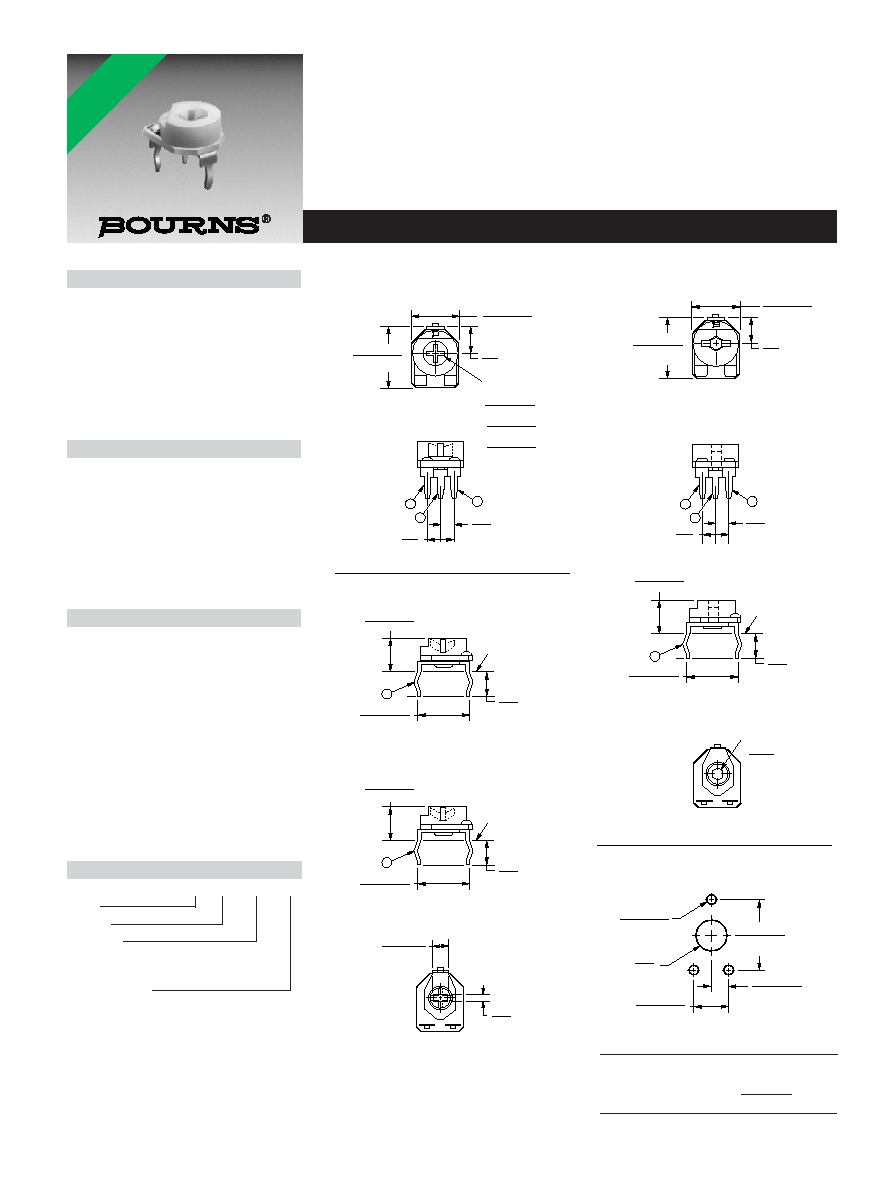
MOUNTING
SURFACE
HEX THRU HOLE
2.0
(.079 )
3319P-3 Both Sides Adjust/Hex
9.0 ± .51
(.354 ± .020)
11.5 ± .51
(.453 ± .020)
1
3
2
6.35 ± .51
(.250 ± .020)
10.34 ± .51
(.407 ± .020)
4.0
(.157)
MOUNTING
SURFACE
3319P Common Dimensions
3319P-1 Top Adjust
3319P-2 Both Sides Adjust/Cross Slot
2.29 ± .51
(.090 ± .020)
1.2
(.047)
2
2
SUGGESTED PWB LAYOUT - 3319P
1.2 ± .18
(.047 ± .007)
10.0 ± .18
(.394 ± .007)
ADJ.
CROSS SLOT
.80 ± .15
(.031 ± .006)
2.0 ± .15
(.079 ± .006)
3.4 ± .15
(.134 ± .006)
11.5 ± .51
(.453 ± .020)
WIDE
X
X
DEEP
LONG
5.0
(.197)
5.0
(.197)
5.0
(.197)
9.0 ± .51
(.354 ± .020)
2.5
(.098)
5.0
(.197)
2.5
(.098)
4.0
(.157)
4.0
(.157)
5.8 ± .51
(.228 ± .020)
5.8 ± .51
(.228 ± .020)
10.34 ± .51
(.407 ± .020)
4.0
(.157)
MOUNTING
SURFACE
2
10.34 ± .51
(.407 ± .020)
2.5 ± .18
(.098 ± .007)
5.0 ± .18
(.197 ± .007)
DIA. 3 PLCS.
DIA. -2, -3 ONLY
ACROSS FLATS
How To Order
3319 W - 2 - 103
Model
Pin Style
Rotor Style
-1 = Standard
-2 = Cross Slot/Single Slot Rear Adjust
-3 = 2mm Hex Thru Hole
Resistance Code
3319 - 9 mm Round Trimming Potentiometer
Features
9 mm Round / Single Turn / Carbon
Commercial / Open Frame
Both sides adjust
Cross slot and hexagon adjustment
designs
Horizontal and vertical mounting styles
Dust resistant/splash resistant covers
PC board stand-offs and retention feature
RoHS compliant*
Electrical Characteristics
Standard Resistance Range
.................................100 to 1 megohm
(see standard resistance table)
Resistance Tolerance ............±25 % std.
End Resistance
...................2 % max. (2K = 30 ohms)
Contact Resistance Variation
..............................................3 % max.
Resolution.....................................Infinite
Adjustment Angle ..................235 ∞ nom.
Environmental Characteristics
Power Rating (200 volts max.)
70 ∞C........................................0.2 watt
Temperature Range
.................................-25 ∞C to +100 ∞C
Temperature Coefficient
......................................±1000 ppm/∞C
Load Life
..............1,000 hours 0.2 watt @ 70 ∞C
(<100K = +3/-7 % TR)
(100K = +3/-10 % TR)
Physical Characteristics
Torque (Operating)
.........................................5 oz-in. max.
Stop Strength
....................................11.0 oz -in. min.
Terminals ........................Solderable pins
Marking ...........................Manufacturer's
trademark, resistance code
Standard Packaging
..................................200 pcs. per bag
Adjustment Tool ..............................H-90
Aqueous cleaning not recommended
DIMENSIONS ARE:
MM
(INCHES)
TOLERANCES: ± 0.25 (.010) EXCEPT WHERE NOTED
*RoHS COMPLIANT
Specifications are subject to change without notice.
Customers should verify actual device performance in their specific applications.
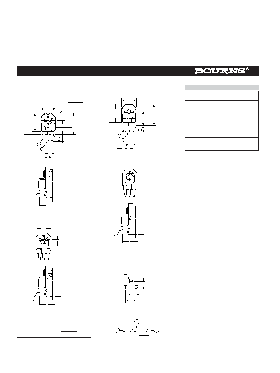
Side Adjust
3319W-1
1
3
2
3319W-3 Both Sides Adjust/Hex
1
3
2
MOUNTING
SURFACE
12.5 ± .51
(.492 ± .020)
2
2.50
(.098)
4.22
(.166)
3319W-2 Both Sides Adjust /Cross Slot
2.29
(.090)
MOUNTING
SURFACE
SUGGESTED PWB LAYOUT - 3319W
9.0 ± .51
(.354 ± .020)
9.0 ± .51
(.354 ± .020)
11.0 ± .51
(.433 ± .020)
12.5 ± .51
(.492 ± .021)
11.0 ± .51
(.433 ± .020)
8.0 ± .51
(.315 ± .020)
8.0 ± .51
(.315 ± .020)
5.0
(.197)
5.0
(.197)
2.5
(.098)
2.5
(.098)
4.0
(.157)
4.0
(.157)
.71
(.028)
2.50
(.098)
2.50
(.098)
2
4.72
(.186)
2
4.22
(.166)
2.5 ± .18
(.098 ± .007)
2.5 ± .18
(.098 ± .007)
5.0 ± .18
(.197 ± .007)
1.20 ± .18
(.047 ± .007)
DIA. 3 PLCS.
HEX THRU HOLE ACROSS FLATS
2.0
(.079)
ADJ.
CROSS SLOT
.80 ± .15
(.031 ± .006)
2.0 ± .15
(.079 ± .006)
3.4 ± .15
(.134 ± .006)
WIDE
X
X
DEEP
LONG
1
3
CW
CLOCKWISE
CCW
2
WIPER
DIMENSIONS ARE:
MM
(INCHES)
TOLERANCES: ± 0.25 (.010) EXCEPT WHERE NOTED
3319 - 9 mm Round Trimming Potentiometer
Resistance
Resistance
(Ohms)
Code
100
101
200
201
500
501
1,000
102
2,000
202
5,000
502
10,000
103
20,000
203
50,000
503
100,000
104
200,000
204
500,000
504
1,000,000
105
Standard Resistance Table
Popular distribution resistance values listed in
boldface.
REV. 11/04