*RoHS Directive 2002/95/EC Jan 27 2003 including Annex
Specifications are subject to change without notice.
Customers should verify actual device performance in their specific applications.
3590 - Precision Potentiometer
Features
Bushing mount
Optional AR pin feature
Plastic or metal shaft and bushings
Wirewound
Solder lugs or PC pins
Sealable (Full body seal)
Designed for use in
HMI applications
Electrical Characteristics
1
Standard Resistance Range........................................................................................200 to 100 K ohms
Total Resistance Tolerance................................................................................................................±5 %
Independent Linearity...................................................................................................................±0.25 %
Effective Electrical Angle ...............................................................................................3600 ∞ +10 ∞, -0 ∞
Absolute Minimum Resistance .....................................1 ohm or 0.1 % maximum (whichever is greater)
Noise .................................................................................................................100 ohms ENR maximum
Dielectric Withstanding Voltage (MIL-STD-202, Method 301)
Sea Level ..............................................................................................................1,500 VAC minimum
Power Rating (Voltage Limited By Power Dissipation or 450 VAC, Whichever is Less)
+40 ∞C ........................................................................................................................................2 watts
+125 ∞C........................................................................................................................................0 watt
Insulation Resistance (500 VDC) ......................................................................1,000 megohms minimum
Resolution .............................................................................................See recommended part numbers
Environmental Characteristics
1
Operating Temperature Range .......................................................................................+1 ∞C to +125 ∞C
Storage Temperature Range .........................................................................................-55 ∞C to +125 ∞C
Temperature Coefficient Over Storage Temperature Range
2
...........................±50 ppm/∞C maximum/unit
Vibration..............................................................................................................................................15 G
Wiper Bounce ...............................................................................................0.1 millisecond maximum
Shock..................................................................................................................................................50 G
Wiper Bounce ...............................................................................................0.1 millisecond maximum
Load Life ...................................................................................................................1,000 hours, 2 watts
Total Resistance Shift...................................................................................................±2 % maximum
Rotational Life (No Load) ................................................................................1,000,000 shaft revolutions
Total Resistance Shift...................................................................................................±5 % maximum
Moisture Resistance (MIL-STD-202, Method 103, Condition B)
Total Resistance Shift...................................................................................................±2 % maximum
IP Rating
Sealed Versions (-3, -4, -7, and -8) ...............................................................................................IP 65
Unsealed Versions (-1 -2, -5, and -6) ............................................................................................IP 40
Mechanical Characteristics
1
Stop Strength .............................................................................................45 N-cm (64 oz.-in.) minimum
Mechanical Angle...........................................................................................................3600 ∞ +10 ∞, -0 ∞
Torque (Starting & Running).................................................0.35 N-cm (0.5 oz.-in.) maximum (unsealed)
1.1 N-cm (1.5 oz.-in.) maximum (sealed)
Mounting ............................................................................................55-80 N-cm (5-7 lb.-in.) (plastic)
170-200 N-cm (15-18 in.-lb.) (metal)
Shaft Runout ......................................................................................................0.13 mm (0.005 in.) T.I.R.
Lateral Runout....................................................................................................0.20 mm (0.008 in.) T.I.R.
Shaft End Play ...................................................................................................0.25 mm (0.010 in.) T.I.R.
Shaft Radial Play................................................................................................0.13 mm (0.005 in.) T.I.R.
Pilot Diameter Runout........................................................................................0.08 mm (0.003 in.) T.I.R.
Backlash ............................................................................................................................1.0 ∞ maximum
Weight ........................................................................................................................Approximately 19 G
Terminals ................................................................................................................Solder lugs or PC pins
Soldering Condition
Manual Soldering ..............................................................96.5Sn/3.0Ag/0.5Cu solid wire or no-clean
rosin cored wire; 370 ∞C (700 ∞F) max. for 3 seconds
Wave Soldering ........................96.5Sn/3.0Ag/0.5Cu solder with no-clean flux; 260 ∞C (500 ∞F) max.
for 5 seconds
Wash processes ......................................................................................................Not recommended
Marking......................................................Manufacturer's name and part number, resistance value and
tolerance, linearity tolerance, wiring diagram, and date code.
Ganging (Multiple Section Potentiometers) .....................................................................1 cup maximum
Hardware...........................One lockwasher and one mounting nut is shipped with each potentiometer.
Recommended Part Numbers
Resistance
Resolution
(Printed Circuit)
(Solder Lug)
(Solder Lug)
()
(%)
3590P-2-102L
3590S-2-102L
3590S-1-102L
1,000
.029
3590P-2-202L
3590S-2-202L
3590S-1-202L
2,000
.023
3590P-2-502L
3590S-2-502L
3590S-1-502L
5,000
.025
3590P-2-103L
3590S-2-103L
3590S-1-103L
10,000
.020
3590P-2-203L
3590S-2-203L
3590S-1-203L
20,000
.019
3590P-2-503L
3590S-2-503L
3590S-1-503L
50,000
.013
3590P-2-104L
3590S-2-104L
3590S-1-104L
100,000
.009
2
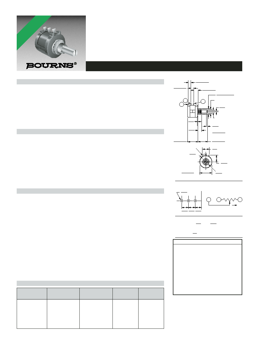
1
3
BUSHING DIAMETER
(SEE PART NUMBERS)
SHAFT DIAMETER
(SEE PART NUMBERS)
1
3
CCW
CW
CW
2
STANDOFFS
12.70
(.500)
MOUNTING SURFACE
15.54
(.612)
RECOMMENDED PC BOARD MOUNTING HOLE LOCATIONS
FMS
5.08 ± .38
(.200 ± .015)
6.99 ± .38
(.275 ± .015)
5.08 ± .38
(.200 ± .015)
10.31 + .00/- .13
(.406+.000/-.005)
.25
(.010)
1.19
(.047)
.81 ± .25
(.032 ± .010)
(METAL VERSIONS)
7.92
(.312)
.81
(.032)
20.62 ± .81
(.812 ± .032)
18.6 ± .4
(.732 ± .015)
12.2
(.48)
11.81
(.465)
DIA.
22 ± .38
(.875 ±.015)
DIA.
HOLE DIAMETER
2.08
(.082)
5.08
(.200)
5.08
(.200)
6.99
(.275)
TOLERANCES: EXCEPT WHERE NOTED
.51 .13
DECIMALS: .XX ±
(.02),
.XXX ±
(.005)
FRACTIONS: ±1/64
MM
DIMENSIONS:
(IN.)
(PLASTIC VERSIONS)
R
SHAFT & BUSHING CONFIGURATIONS
(Bushing - DxL, Shaft - D)
(-1) Plastic Bushing (3/8 " x 5/16 ")
and Shaft (.2480 + .001, - .002)
(-2) Metal Bushing (3/8 x 5/16 )
and Shaft (.2497 + .0000, - .0009)
(-3) Sealed, Plastic Bushing (3/8 " x 5/16 ")
and Shaft (.2480 + .001, - .002)
(-4) Sealed, Metal Bushing (3/8 " x 5/16 ")
and Shaft (.2497 + .0000, - .0009)
(-5) Metric, Plastic Bushing (9 mm x 7.94 mm)
and Shaft (6 mm + 0, - .076 mm)
(-6) Metric, Metal Bushing (9 mm x 7.94 mm)
and Shaft (6 mm + 0, - .023 mm)
(-7) Metric, Sealed, Plastic Bushing (9 mm x
7.94 mm) and Shaft (6 mm + 0, - .076 mm)
(-8) Metric, Sealed, Metal Bushing (9 mm x
7.94 mm) and Shaft (6 mm + 0, - .023 mm)
BOLDFACE LISTINGS ARE IN STOCK AND READILY
AVAILABLE THROUGH DISTRIBUTION.
FOR OTHER OPTIONS CONSULT FACTORY.
TERMINALS:
L = RoHS COMPLIANT
BLANK = STANDARD
REV. 06/06
NOTE: For Anti-rotation pin add 91 after configuration dash number. Example: -2 becomes -291 to add AR pin.
*RoHS COMPLIANT
VERSIONS
AVAILABLE