*RoHS Directive 2002/95/EC Jan 27 2003 including Annex
Specifications are subject to change without notice.
Customers should verify actual device performance in their specific applications.
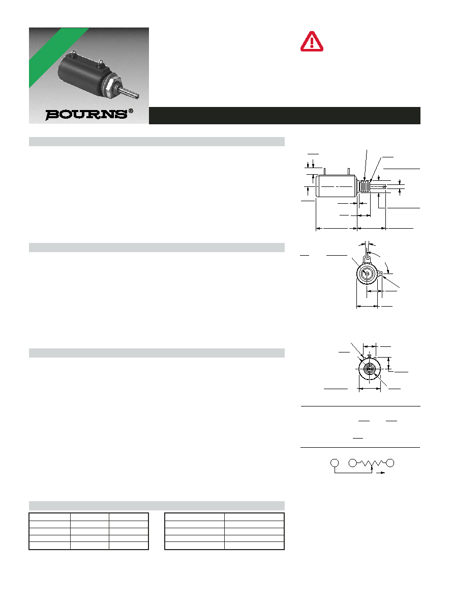
3700/3701 - Precision Potentiometer
Features
Bushing mount
Excellent resolution
Non-standard features and specifications
available
Small diameter
High rotational life
Electrical Characteristics
1
3700 Wirewound Element 3701 Hybritron
§
Element
Standard Resistance Range ..............100 to 100 K ohms ..................1 K to 100 K ohms
Total Resistance Tolerance ................±5 % ........................................±10 %
Independent Linearity ........................±0.25 % ....................................±0.25 %
Effective Electrical Angle ....................3600 ∞ +10 ∞, -0 ∞ ....................3600 ∞ +10 ∞, -2 ∞
Absolute Minimum Resistance/..........1 ohm or 0.1 % maximum........Minimum voltage
Minimum Voltage
(whichever is greater)
0.2 % maximum
Noise ..................................................500 ohms ENR maximum ........Output smoothness 0.1 %
maximum
Dielectric Withstanding Voltage (MIL-STD-202, Method 301)
Sea Level ........................................1,000 VAC minimum ................1,000 VAC minimum
Power Rating (Voltage Limited By Power Dissipation or 315 VAC, Whichever Is Less)
+70 ∞C ............................................1 watt........................................1 watt
+125 ∞C ..........................................0 watt........................................0 watt
Insulation Resistance (500 VDC) ........1,000 megohms minimum ........1,000 megohms minimum
Resolution ............................................See recommended part nos. ....Essentially infinite
Environmental Characteristics
1
Operating Temperature Range ..........+1 ∞C to +125 ∞C ......................+1 ∞C to +105 ∞C
Storage Temperature Range ..............-65 ∞C to +125 ∞C ....................-55 ∞C to +105 ∞C
Temperature Coefficient Over
Storage Temperature Range
2
........±50 ppm/∞C maximum/unit ......±100 ppm/∞C maximum/unit
Vibration..............................................20 G ..........................................20 G
Wiper Bounce ................................0.1 millisecond maximum ........0.1 millisecond maximum
Shock..................................................100 G ........................................100 G
Wiper Bounce ................................0.1 millisecond maximum ........0.1 millisecond maximum
Load Life ............................................1,000 hours, 1 watt ..................1,000 hours, 1 watt
Total Resistance Shift ....................±2 % maximum ........................±5 % maximum
Rotational Life (No Load) ....................1,000,000 shaft revolutions
2
....4,000,000 shaft revolutions
2
Total Resistance Shift ....................±5 % maximum ........................±5 % maximum
Moisture Resistance (MIL-STD-202, Method 103, Condition B)
Total Resistance Shift ....................±2 % maximum ........................±5 % maximum
IP Rating ............................................IP 40 ........................................IP 40
Mechanical Characteristics
1
Stop Strength ...............................................................................................14 N-cm (20 oz-in.) minimum
Mechanical Angle ......................................................................................................3600 ∞ +20 ∞, -0 ∞
Torque (Starting & Running)......................................................................0.45 N-cm (0.6 oz.-in.) max.
Mounting.....................................................................................170-200 N-cm (15-18 lb.-in.) max.
Shaft Runout..................................................................................................0.05 mm (0.002 in.) T.I.R.
Lateral Runout ...............................................................................................0.13 mm (0.005 in.) T.I.R.
Shaft End Play ...............................................................................................0.13 mm (0.005 in.) T.I.R.
Shaft Radial Play ...........................................................................................0.08 mm (0.003 in.) T.I.R.
Pilot Diameter Runout ...................................................................................0.05 mm (0.002 in.) T.I.R.
Backlash ........................................................................................................................1.0 ∞ maximum
Weight..................................................................................................................Approximately 28 gm
Terminals ............................................Gold-plated solderlugs (3700) or gold-plated turret lugs (3701)
Soldering Condition ....................Recommended hand soldering using Sn95/Ag5 no clean solder,
0.025 " wire diameter. Maximum temperature 399 ∞C (750 ∞F) for 3 seconds.
No wash process to be used with no clean flux.
Marking .................................................Manufacturer's name and part number, resistance value and
tolerance, linearity tolerance, wiring diagram, and date code
Ganging (Multiple Section Pots.) .................................................................................1 cup maximum
Hardware ...................................................One lockwasher (H-37-1) and one mounting unit (H-38-1)
is shipped with each potentiometer.
1
At room ambient: +25 ∞C nominal and 50 % relative humidity nominal, except as noted.
2
Consult manufacturer for complete specification details.
Recommended Part Numbers
Part Number
Resistance ()
Resolution
3700S-1-102L
1,000
0.43
3700S-1-202L
2,000
0.35
3700S-1-502L
5,000
0.34
3700S-1-103L
10,000
0.26
Part Number
Resistance ()
3701H-1-102L
1,000
3701H-1-202L
2,000
3701H-1-502L
5,000
3701H-1-103L
10,000
1
3
CCW
CW
CW
2
12.2
(.48)
STANDOFFS
11.81
(.465)
12.70
(.500)
MOUNTING
SURFACE
3700S-1/3701H-1
3.30
(.13)
11.11
(7/16)
CCW
CW
1/4"-32-UNEF-2ATHD
1.52
(.06)
WIPER
90 ∞ ± 5 ∞
7 ∞ ± 2 ∞
LOCKWASHER AND MOUNTING NUT
TO BE SUPPLIED WITH EACH UNIT
.28
(9/32)
25.40 ± .51
(1.00 ± .02)
2.37 + .00/- .01
(.0935+.0000/-.0003)
DIA.
7.14 + .00/- .01
(.281+.000/-.002)
DIA.
17.46 ± .80
(11/16 ± 1/32)
ADJUSTMENT SLOT
.81
WIDE X
.81 ± .25 DEEP
(.032)
(.032 ± .010)
9.53
(3/8)
12.7
(1/2)
15.54
(.612)
R
DIA.
DIA.
22.23 ± .38
(.875 ± .015)
TOLERANCES: EXCEPT WHERE NOTED
.25 .13
DECIMALS: .XX ±
(.010),
.XXX ±
(.005)
FRACTIONS: ±1/64
MM
DIMENSIONS:
(IN)
.25
(.010)
X 45 ∞ CHAMFER
BOLDFACE LISTINGS ARE IN STOCK AND READILY
AVAILABLE THROUGH DISTRIBUTION.
FOR OTHER OPTIONS CONSULT FACTORY.
TERMINALS:
L = RoHS COMPLIANT
BLANK = STANDARD
REV. 06/06
Models 3700 and 3701 are currently
available, although not recommended
for new designs.
*RoHS COMPLIANT
VERSIONS
AVAILABLE