4600H Series - Thick Film Conformal SIPs
Specifications are subject to change without notice.
Customers should verify actual device performance in their specific applications.
Product Characteristics
Resistance Range
......................10 ohms to 10 megohms
Maximum Operating Voltage..........100 V
Temperature Coefficient of Resistance
50 to 2.2 M................±100 ppm/∞C
below 50 ......................±250 ppm/∞C
above 2.2 M..................±250 ppm/∞C
TCR Tracking .........................50 ppm/∞C
maximum; equal values
Resistor Tolerance ................See circuits
Insulation Resistance
..................10,000 megohms minimum
Dielectric Withstanding Voltage
.............................................200 VRMS
Operating Temperature
.................................-55 ∞C to +125 ∞C
Environmental Characteristics
TESTS PER MIL-STD-202........ R MAX.
Short Time Overload..................±0.25 %
Load Life ....................................±1.00 %
Moisture Resistance ..................±0.50 %
Resistance to Soldering Heat ....±0.25 %
Terminal Strength.......................±0.25 %
Thermal Shock...........................±0.25 %
Physical Characteristics
Flammability .........Conforms to UL94V-0
Body Material........................Epoxy resin
Standard Packaging
....................Bulk, Ammo-pak available
WATTS
AMBIENT TEMPERATURE ( C )
∞
0
70
125
3.50
3.00
2.50
2.00
1.50
1.00
.50
25
4612H
4608H
4606H
4614H
4604H
4610H
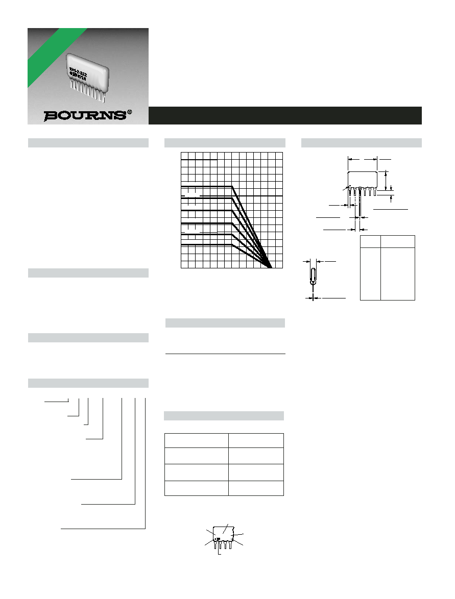
Package Power Ratings (Watts)
Ambient
Ambient
Temperature
Temperature
Pkg.
70
∞C Pkg.
70
∞C
4604H
0.80
4610H
2.00
4605H
1.00
4611H
2.20
4606H
1.20
4612H
2.40
4607H
1.40
4613H
2.60
4608H
1.60
4614H
2.80
4609H
1.80
A
MAXIMUM
PIN #1
REF.
8.89
(.350)
1.24
(.049)
MAX.
BOTH ENDS
.508 ± .050
(.020 ± .002)
TYP.
2.54 ± .07
(.100 ± .003*)
TYP.
NON-ACCUM.
2.49
(.098)
MAX.
.254 ± .050
(.010 ± .002)
TYP.
Maximum package length is equal to 2.54mm (.100") times the
number of pins, less .005mm (.002").
Governing dimensions are in metric. Dimensions in parentheses
are inches and are approximate.
*Terminal centerline to centerline measurements made at point of
emergence of the lead from the body.
MAX.
3.43 +.38/ -.508
(.135 +.015/ -.020)
NUMBER OF PINS
6H-2-222
YYWW
CIRCUIT
RESISTANCE
CODE
PIN ONE
INDICATOR
MANUFACTURER'S
TRADEMARK
DATE CODE
Typical Part Marking
Represents total content. Layout may vary.
How To Order
46 06 H - 101 - 222 __ __
Model
(46 = Conformal SIP)
Number of Pins
Physical Configuration
(H = Thick Film High Profile)
Electrical Configuration
∑ 101 = Bussed
∑ 102 = Isolated
∑ 104 = Dual Terminator
∑ AP1 = Bussed Ammo**
∑ AP2 = Isolated Ammo**
∑ AP4 = Dual Ammo**
Resistance Code
∑ First 2 digits are significant
∑ Third digit represents the
number of zeros to follow.
Resistance Tolerance
∑ Blank = ±2 % (see "Resistance Tolerance"
on next page for resistance range)
∑ F = ±1 % (100 ohms - 5 megohms)
Terminations
∑ All electrical configurations EXCEPT 104 & AP4:
LF = Sn/Ag/Cu-plated (lead free)
∑ ONLY electrical configurations 104 & AP4:
L = Sn/Ag/Cu-plated (lead free)
∑ Blank = Tin/Lead-plated
Consult factory for other available options.
**Available for packages with 10 pins or less.
Part Number
Part Number
4606H-101-RC
6H-1-RC
4608H-102-RC
8H-2-RC
4610H-104-RC/RC
10H-4-RC/RC
RC = ohmic value, 3-digit resistance code.
Pin
A Maximum
Count
mm (Inches)
4
10.11 (.398)
5
12.65 (.498)
6
15.19 (.598)
7
17.73 (.698)
8
20.27 (.798)
9
22.81 (.898)
10
25.35 (.998)
11
27.89 (1.098)
12
30.43 (1.198)
13
32.97 (1.298)
14
35.51 (1.398)
Package Power Temp. Derating Curve
Product Dimensions
Features
Lead free version available (see How to
Order "Termination" option)
RoHS compliant (lead free version)*
High profile offers increased power
handling
Wide assortment of pin packages
enhances design flexibility
Ammo-pak packaging available
Recommended for rosin flux and solvent
clean or no clean flux processes
Marking on contrasting background for
permanent identification
*RoHS COMPLIANT
VERSIONS
AVAILABLE
*RoHS Directive 2002/95/EC Jan 27 2003 including Annex
For Standard Values Used in Capacitors,
Inductors, and Resistors,
click here
.
Specifications are subject to change without notice.
Customers should verify actual device performance in their specific applications.
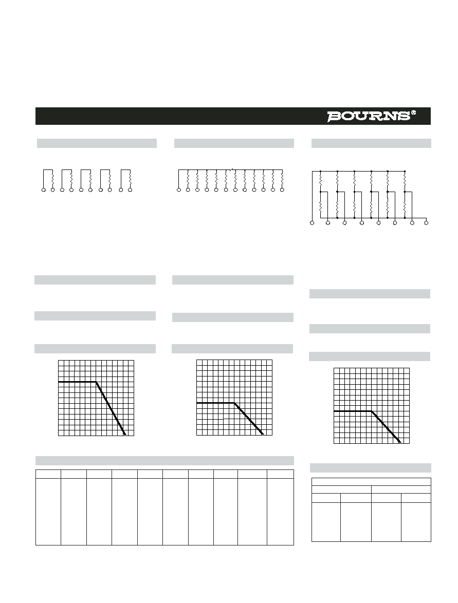
Isolated Resistors (102 Circuit)
Model 4600H-102
4, 6, 8, 10, 12 or 14 Pin
Bussed Resistors (101 Circuit)
Model 4600H-101-RC
4 through 14 Pin
Dual Terminator (104 Circuit)
Model 4600H-104-R1/R2
4 through 14 Pin
1
4
6
12
14
...
1
14
1
8
R2
R1
R2
R1
R2
R1
R2
R1
R2
R1
R2
R1
These models incorporate 2 to 7
isolated thick-film resistors of equal
value, each connected between two
pins.
Resistance Tolerance
10 ohms to 49 ohms ...................±1 ohm
50 ohms to 5 megohms.................±2 %*
Above 5 megohms..........................±5 %
Power Rating per Resistor
At 70 ∞C ...................................0.50 watt
WATTS
AMBIENT TEMPERATURE ( C )
∞
0
70
125
.50
.40
.30
.20
.10
25
.60
.70
These models incorporate 3 to 13
thick-film resistors of equal value, each
connected between a common bus
(pin 1) and a separate pin.
Resistance Tolerance
10 ohms to 49 ohms ...................±1 ohm
50 ohms to 5 megohms ................±2 %*
Above 5 megohms .........................±5 %
Power Rating per Resistor
At 70 ∞C ...................................0.30 watt
WATTS
AMBIENT TEMPERATURE ( C )
∞
0
70
125
.50
.40
.30
.20
.10
25
.60
.70
The 4608H-104 (shown above) is an 8-
pin configuration and terminates 6 lines.
Pins 1 and 8 are common for ground and
power, respectively. Twelve thick-film
resistors are paired in series between the
common lines (pins 1 and 8).
Resistance Tolerance
Below 100 ohms .......................±2 ohms
100 ohms to 5 megohms ..............±2 %*
Above 5 megohms .........................±5 %
Power Rating per Resistor
At 70 ∞C ...................................0.30 watt
WATTS
AMBIENT TEMPERATURE ( C )
∞
0
70
125
.50
.40
.30
.20
.10
25
.60
.70
Popular Resistance Values
(101, 102 Circuits)
**
* ±1 % TOLERANCE IS AVAILABLE BY ADDING SUFFIX CODE "F" AFTER THE RESISTANCE CODE.
**NON-STANDARD VALUES AVAILABLE, WITHIN RESISTANCE RANGE.
Ohms
Code
Ohms
Code
Ohms
Code
Ohms
Code
Ohms
Code
10
100
180
181
1,800
182
15,000
153
120,000
124
22
220
220
221
2,000
202
18,000
183
150,000
154
27
270
270
271
2,200
222
20,000
203
180,000
184
33
330
330
331
2,700
272
22,000
223
220,000
224
39
390
390
391
3,300
332
27,000
273
270,000
274
47
470
470
471
3,900
392
33,000
333
330,000
334
56
560
560
561
4,700
472
39,000
393
390,000
394
68
680
680
681
5,600
562
47,000
473
470,000
474
82
820
820
821
6,800
682
56,000
563
560,000
564
100
101
1,000
102
8,200
822
68,000
683
680,000
684
120
121
1,200
122
10,000
103
82,000
823
820,000
824
150
151
1,500
152
12,000
123
100,000
104
1,000,000
105
Popular Resistance Values
(104 Circuit)
**
Resistance
(Ohms)
Code
R
1
R
2
R
1
R
2
160
240
161
241
180
390
181
391
220
270
221
271
220
330
221
331
330
390
331
391
330
470
331
471
3,000
6,200
302
622
4600H Series - Thick Film Conformal SIPs
Power Temperature Derating Curve
Power Temperature Derating Curve
Power Temperature Derating Curve
REV. 06/06
For information on specific applications,
download Bourns' application notes:
DRAM Applications
Dual Terminator Resistor Networks
R/2R Ladder Networks
SCSI Applications