*RoHS Directive 2002/95/EC Jan 27 2003 including Annex
Specifications are subject to change without notice.
Customers should verify actual device performance in their specific applications.
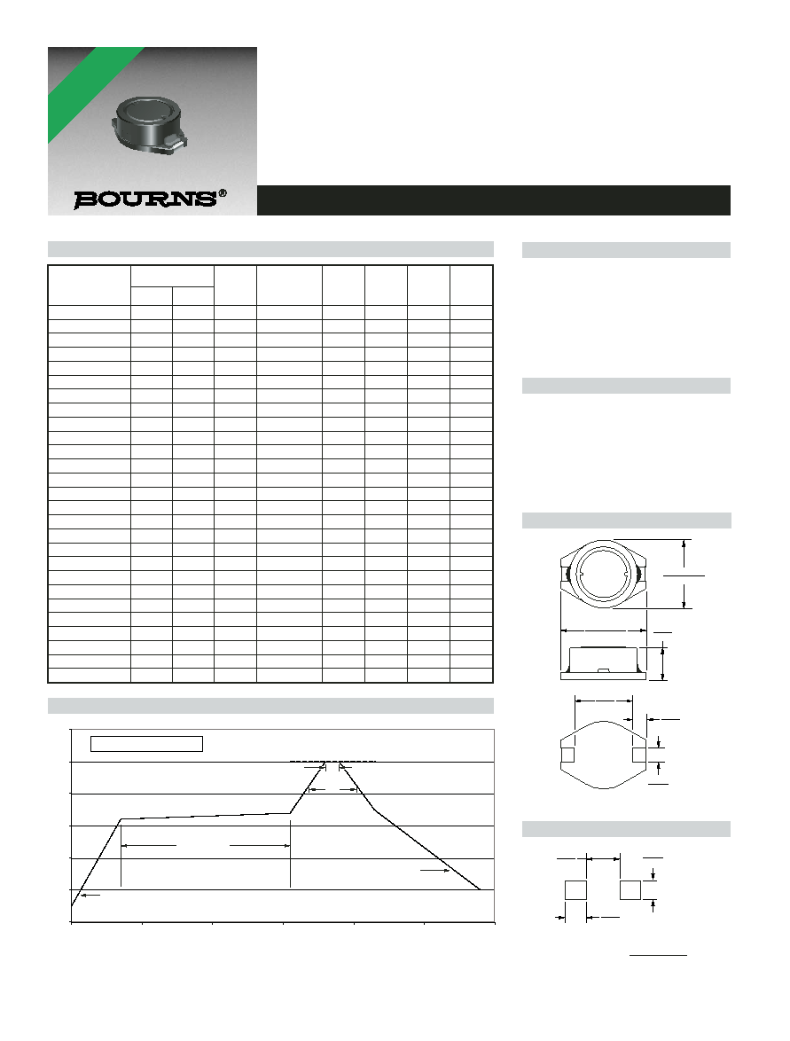
7.3
(.287)
12.7 ± 0.1
(.500 ± .004)
7.6
(.299)
TYP.
3.0
(.118)
2.5
(.098)
TYP.
3.0
(.118)
MAX.
10.3 ± 0.2
(.406 ± .008)
2.8
(.110)
2.5
(.098)
TYP.
101
SRR1003 Series - Shielded Power Inductors
Features
Available in E6 series
Low profile of 3 mm
High current
Lead free
RoHS compliant*
Applications
Input/output of DC/DC converters
Power supplies for:
·
Portable communication equipment
·
Camcorders
·
LCD TVs
·
Car radios
Electrical Specifications
Product Dimensions
Recommended Layout
General Specifications
Test Voltage ........................................1 V
Reflow soldering.....250 °C; 10 sec max.
(In compliance with JEDEC,
J-STD-020C, Table 4-2)
Operating Temperature .-40 °C to +125 °C
(Temperature rise included)
Storage Temperature..-40 °C to +125 °C
Resistance to Soldering Heat
............................250 °C, 10 sec. max.
Materials
Core.....................Ferrite DR and RI core
Wire .............................Enameled copper
Base ......................................LCP E4008
Terminal ....................................Cu/Ni/Sn
Rated Current
....................Ind. drop 10 % typ. at Isat
Temperature Rise
......................40 °C max. at rated Irms
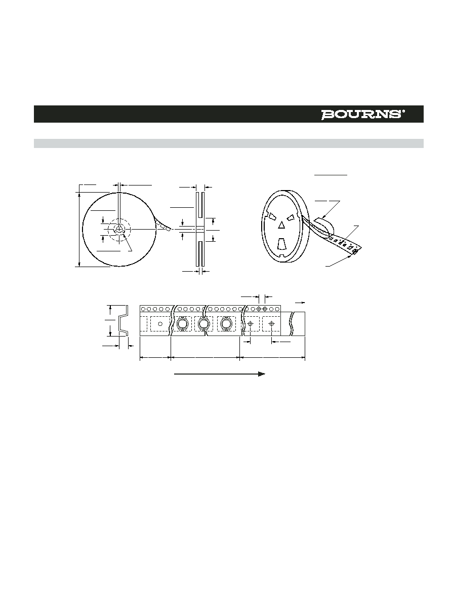
Packaging...................1000 pcs. per reel
Inductance 1kHz
Q
Test
SRF
RDC
I rms
I sat
Bourns Part No.
(µH)
Tol. %
Ref.
Frequency
Min.
(
)
Max.
Typ.
(MHz)
(MHz)
(A)
(A)
SRR1003-1R8M
1.8
± 20
10
7.96M
100.0
0.03
3.00
8.00
SRR1003-2R2M
2.2
± 20
11
7.96M
90.0
0.045
2.76
6.70
SRR1003-3R0M
3.0
± 20
11
7.96M
70.0
0.062
2.20
5.60
SRR1003-3R9M
3.9
± 20
10
7.96M
60.0
0.07
2.10
5.20
SRR1003-4R7M
4.7
± 20
10
7.96M
50.0
0.08
1.90
4.60
SRR1003-7R5M
7.5
± 20
10
7.96M
32.0
0.10
1.44
3.90
SRR1003-100M
10
± 20
18
2.52M
28.0
0.15
1.24
3.30
SRR1003-120M
12
± 20
20
2.52M
26.0
0.19
1.10
3.00
SRR1003-150M
15
± 20
20
2.52M
25.0
0.20
1.02
2.60
SRR1003-180M
18
± 20
20
2.52M
14.0
0.27
0.90
2.50
SRR1003-220M
22
± 20
17
2.52M
22.0
0.30
0.85
2.10
SRR1003-270M
27
± 20
17
2.52M
19.0
0.40
0.75
1.90
SRR1003-330M
33
± 20
17
2.52M
17.0
0.45
0.70
1.70
SRR1003-390M
39
± 20
18
2.52M
16.0
0.56
0.65
1.60
SRR1003-470M
47
± 20
18
2.52M
14.0
0.65
0.60
1.40
SRR1003-560M
56
± 20
15
2.52M
13.0
0.68
0.52
1.30
SRR1003-680M
68
± 20
15
2.52M
11.0
0.80
0.48
1.20
SRR1003-820M
82
± 20
20
2.52M
11.0
1.20
0.42
1.00
SRR1003-101M
100
± 20
23
0.796M
10.0
1.40
0.40
0.95
SRR1003-121M
120
± 20
22
0.796M
9.0
1.52
0.35
0.85
SRR1003-151M
150
± 20
23
0.796M
8.0
1.80
0.32
0.80
SRR1003-181M
180
± 20
20
0.796M
7.0
2.20
0.28
0.75
SRR1003-221M
220
± 20
20
0.796M
6.0
2.20
0.26
0.65
SRR1003-271Y
270
± 15
26
0.796M
4.1
3.10
0.22
0.60
SRR1003-331Y
330
± 15
26
0.796M
3.6
3.60
0.20
0.55
SRR1003-391Y
390
± 15
28
0.796M
2.6
4.60
0.18
0.46
SRR1003-471Y
470
± 15
28
0.796M
2.1
5.10
0.16
0.45
DIMENSIONS:
MM
(INCHES)
Soldering Profile
0
50
100
150
200
250
300
0
50
100
150
200
250
300
Time
(seconds)
T
e
mperature (°C)
<2> Max. of 30 seconds > 220 °C
<1> Max. of 10 seconds at 250 °C
250 °C
<2>
<1>
120 - 150 seconds
Ramp-up
4 °/second maximum
Ramp-down
5 °C/second maximum
*RoHS COMPLIANT