Document Outline
- FEATURES
- APPLICATIONS
- DESCRIPTION
- ABSOLUTE MAXIMUM RATINGS(
- ORDERING INFORMATION(1)
- RELATED PRODUCTS
- RECOMMENDED OPERATING CONDITIONS
- REFERENCE SELECTION
- ELECTRICAL CHARACTERISTICS
- AC CHARACTERISTICS
- LVDS DIGITAL DATA AND CLOCK OUTPUTS
- SWITCHING CHARACTERISTICS
- SERIAL INTERFACE TIMING
- LVDS TIMING DIAGRAM (PER ADC CHANNEL)
- RESET TIMING
- POWER-DOWN TIMING
- PIN CONFIGURATION
- PIN DESCRIPTIONS
- TYPICAL CHARACTERISTICS
- THEORY OF OPERATION
- OVERVIEW
- DRIVING THE ANALOG INPUTS
- INPUT OVER-VOLTAGE RECOVERY
- REFERENCE CIRCUIT DESIGN
- CLOCKING
- LVDS BUFFERS
- NOISE COUPLING ISSUES
- POWER-DOWN MODE
- SUPPLY SEQUENCE
- LAYOUT OF PCB WITH POWERPAD THERMALLY ENHANCED PACKAGES

FEATURES
D
Maximum Sample Rate: 40MSPS
D
12-Bit Resolution
D
No Missing Codes
D
Power Dissipation: 907mW
D
CMOS Technology
D
Simultaneous Sample-and-Hold
D
70.5dB SNR at 10MHz IF
D
Internal and External References
D
3.3V Digital/Analog Supply
D
Serialized LVDS Outputs
D
Integrated Frame and Synch Patterns
D
MSB and LSB First Modes
D
Option to Double LVDS Clock Output Currents
D
Pin- and Format-Compatible Family
D
TQFP-80 PowerPAD
Package
APPLICATIONS
D
Portable Ultrasound Systems
D
Tape Drives
D
Test Equipment
D
Optical Networking
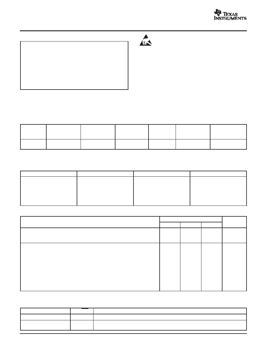
DESCRIPTION
The ADS5270 is a high-performance, 40MSPS, 8-channel,
parallel analog-to-digital converter (ADC). Internal references
are provided, simplifying system design requirements. Low
power consumption allows for the highest of system
integration densities. Serial LVDS (low-voltage differential
signaling) outputs reduce the number of interface lines and
package size.
An integrated phase lock loop multiplies the incoming ADC
sampling clock by a factor of 12. This 12x clock is used in the
process of serializing the data output from each channel. The
12x clock is also used to generate a 1x and a 6x clock, both
of which are transmitted as LVDS clock outputs. The 6x clock
is denoted by the differential pair LCLKP and LCLKN, while the
1x clock is denoted by ADCLKP and ADCLKN. The word
output of each ADC channel can be transmitted either as MSB
or LSB first. The bit coinciding with the rising edge of the 1x
clock output is the first bit of the word. Data is to be latched by
the receiver on both the rising and falling edges of the 6x clock.
The ADS5270 provides internal references, or can optionally
be driven with external references. Best performance can be
achieved through the internal reference mode.
The device is available in a PowerPAD TQFP-80 package and
is specified over a -40
�
C to +85
�
C operating range.
12-Bit
ADC
PLL
S/H
Serializer
1X ADCLK
6X ADCLK
IN1
P
ADCLK
IN1
N
OUT1
P
OUT1
N
12-Bit
ADC
S/H
Serializer
IN2
P
IN2
N
OUT2
P
OUT2
N
12-Bit
ADC
S/H
Serializer
IN3
P
IN3
N
OUT3
P
OUT3
N
LCLK
P
LCLK
N
ADCLK
P
ADCLK
N
12-Bit
ADC
S/H
Serializer
IN4
P
IN4
N
OUT4
P
OUT4
N
12-Bit
ADC
S/H
Serializer
IN5
P
IN5
N
OUT5
P
OUT5
N
12-Bit
ADC
S/H
Serializer
IN6
P
IN6
N
OUT6
P
OUT6
N
12-Bit
ADC
S/H
Serializer
IN7
P
IN7
N
OUT7
P
OUT7
N
12-Bit
ADC
S/H
Serializer
Reference
IN8
P
IN8
N
RE
F
T
INT/EXT
V
CM
RE
F
B
OUT8
P
OUT8
N
Registers
SC
L
K
SD
AT
A
CS
Control
R
ESET
PD
ADS5270
SBAS293D - JANUARY 2004 - REVISED MAY 2004
8-Channel, 12-Bit, 40MSPS ADC
with Serial LVDS Interface
PRODUCTION DATA information is current as of publication date. Products
conform to specifications per the terms of Texas Instruments standard warranty.
Production processing does not necessarily include testing of all parameters.
www.ti.com
Copyright
2004, Texas Instruments Incorporated
Please be aware that an important notice concerning availability, standard warranty, and use in critical applications of Texas Instruments
semiconductor products and disclaimers thereto appears at the end of this data sheet.
PowerPAD is a registered trademark of Texas Instruments. All other trademarks are the property of their respective owners.
ADS5270
SBAS293D - JANUARY 2004 - REVISED MAY 2004
www.ti.com
2
ABSOLUTE MAXIMUM RATINGS
(1)
Supply Voltage Range, AVDD
-0.3V to 3.8V
. . . . . . . . . . . . . . . . . .
Supply Voltage Range, LVDD
-0.3V to 3.8V
. . . . . . . . . . . . . . . . . .
Voltage Between AVSS and LVSS
-0.3V to 0.3V
. . . . . . . . . . . . . .
Voltage Between AVDD and LVDD
-0.3V to 0.3V
. . . . . . . . . . . . . .
Voltages Applied to External REF Pins
-0.3V to 2.4V
. . . . . . . . . .
All LVDS Data and Clock Outputs
-0.3V to 2.4V
. . . . . . . . . . . . . .
Analog Input Pins
-0.3V to 2.7V
. . . . . . . . . . . . . . . . . . . . . . . . . . . .
Peak Total Input Current (all inputs)
-30mA
. . . . . . . . . . . . . . . . . . .
Operating Free-Air Temperature Range, TA
-40
�
C to 85
�
C
. . . . . .
Lead Temperature 1.6mm (1/16
from case for 10s)
220
�
C
. . . . . .
(1) Stresses above these ratings may cause permanent damage.
Exposure to absolute maximum conditions for extended periods
may degrade device reliability. These are stress ratings only, and
functional operation of the device at these or any other conditions
beyond those specified is not supported.
This integrated circuit can be damaged by ESD. Texas
Instruments recommends that all integrated circuits be
handled with appropriate precautions. Failure to observe
proper handling and installation procedures can cause damage.
ESD damage can range from subtle performance degradation to
complete device failure. Precision integrated circuits may be more
susceptible to damage because very small parametric changes could
cause the device not to meet its published specifications.
ORDERING INFORMATION
(1)
PRODUCT
PACKAGE-LEAD
PACKAGE
DESIGNATOR
SPECIFIED
TEMPERATURE
RANGE
PACKAGE
MARKING
ORDERING
NUMBER
TRANSPORT
MEDIA, QUANTITY
ADS5270
HTQFP-80(2)
PFP
-40
�
C to +85
�
C
ADS5270IPFP
ADS5270IPFP
Tray, 96
ADS5270IPFPT
Tape and Reel, 250
(1) For the most current package and ordering information, see the Package Option Addendum located at the end of this data sheet.
(2) Thermal pad size: 4.69mm x 4.69mm (min), 6.20mm x 6.20mm (max).
RELATED PRODUCTS
MODEL
RESOLUTION (BITS)
SAMPLE RATE (MSPS)
CHANNELS
ADS5271
12
50
8
ADS5272
12
65
8
ADS5273
12
70
8
ADS5275
10
40
8
ADS5276
10
50
8
ADS5277
10
65
8
RECOMMENDED OPERATING CONDITIONS
ADS5270
MIN
TYP
MAX
UNIT
SUPPLIES AND REFERENCES
Analog Supply Voltage, AVDD
3.0
3.3
3.6
V
Output Driver Supply Voltage, LVDD
3.0
3.3
3.6
V
CLOCK INPUT AND OUTPUTS
ADCLK Input Sample Rate (low-voltage TTL)
20
40
MSPS
Low Level Voltage Clock Input
0.6
V
High Level Voltage Clock Input
VDD - 0.6
V
ADCLKP and ADCLKN Outputs (LVDS)
20
40
MHz
LCLKP and LCLKN Outputs (LVDS)(1)
120
240
MHz
Operating Free-Air Temperature, TA
-40
+85
�
C
Thermal Characteristics
q
JA
21
�
C/W
q
JC
68
�
C/W
(1) 6
�
ADCLK.
REFERENCE SELECTION
MODE
INT/EXT
DESCRIPTION
2.0VPP Internal Reference
1
Default with internal pull-up.
External Reference
0
Internal reference is powered down. Common mode of external reference should be within
50mV of VCM. VCM is derived from the internal bandgap voltage.

ADS5270
SBAS293D - JANUARY 2004 - REVISED MAY 2004
www.ti.com
3
ELECTRICAL CHARACTERISTICS
TMIN = -40
�
C, and TMAX = +85
�
C. Typical values are at TA = 25
�
C, clock frequency = maximum specified, 50% clock duty cycle, AVDD = 3.3V,
LVDD = 3.3V, -1dBFS, internal voltage reference, and LVDS buffer current at 3.5mA per channel, unless otherwise noted.
ADS5270
PARAMETER
TEST CONDITIONS
MIN
TYP
MAX
UNITS
DC ACCURACY
No Missing Codes
Assured
DNL
Differential Nonlinearity
f
IN
= 5MHz
-0.9
�
0.5
0.9
LSB
INL
Integral Nonlinearity
f
IN
= 5MHz
-2.0
�
0.6
2.0
LSB
Offset Error
(1)
-0.75
�
0.2
0.75
%FS
Offset Temperature Coefficient
14
ppm/
�
C
Fixed Attenuation in Channel
(2)
1
%FS
Variable Attenuation in Channel
(3)
�
0.2
%FS
Gain Error
(4)
REF
T
- REF
B
-2.5
�
1.0
2.5
%FS
Gain Temperature Coefficient
(5)
44
ppm/
�
C
POWER SUPPLY
I
CC
Total Supply Current
V
IN
= FS, F
IN
= 5MHz
275
mA
I(AVDD)
Analog Supply Current
V
IN
= FS, F
IN
= 5MHz
221
mA
I(LVDD)
Digital Output Driver Supply Current
V
IN
= FS, F
IN
= 5MHz, LVDS Into 100
Load
54
mA
Power Dissipation
904
950
mW
Power Down
Clock Running
90
mW
REFERENCE VOLTAGES
VREF
T
Reference Top (internal)
1.95
2.0
2.05
V
VREF
B
Reference Bottom (internal)
0.95
1.0
1.05
V
V
CM
Common-Mode Voltage
1.45
1.5
1.55
V
V
CM
Output Current
(6)
�
50mV Change in Voltage
�
2
mA
VREF
T
Reference Top (external)
1.875
V
VREF
B
Reference Bottom (external)
1.125
V
External Reference Input Current
(7)
2.0
mA
ANALOG INPUT
Differential Input Capacitance
7.0
pF
Analog Input Common-Mode Range
V
CM
�
0.05
V
Differential Input Voltage Range
1.5
2.02
V
PP
Voltage Overload Recovery Time
Differential Input Signal at 4V
PP
Recovery to Within 1% of Code
4.0
CLK Cycles
Input Bandwidth
-3dBFS
300
MHz
DIGITAL DATA OUTPUTS
Data Bit Rate
240
480
MBPS
SERIAL INTERFACE
SCLK
Serial Clock Input Frequency
20
MHz
V
IN
LOW
Input Low Voltage
0
0.6
V
V
IN
HIGH
Input High Voltage
2.1
VDD
V
Input Current
�
10
�
A
Input Pin Capacitance
5.0
pF
(1)
Offset error is the deviation of the average code from mid-code for a zero input. Offset error is expressed in terms of % of full scale.
(2)
Fixed attenuation in the channel arises due to a fixed attenuation of about 1% in the sample-and-hold amplifier. When the differential voltage at the analog input pins are
changed from -V
REF
to +V
REF
, the swing of the output code is expected to deviate from the full-scale code (4096LSB) by the extent of this fixed attenuation.
NOTE: V
REF
is defined as (REF
T
- REF
B
).
(3)
Variable attenuation in the channel refers to the attenuation of the signal in the channel over and above the fixed attenuation.
(4)
The reference voltages are trimmed at production so that (VREF
T
- VREF
B
) is within
�
25mV of the ideal value of 1V. It does not include fixed attenuation.
(5)
The gain temperature coefficient refers to the temperature coefficient of the attenuation in the channel. It does not account for the variation of the reference voltages with
temperature.
(6)
V
CM
provides the common-mode current for the inputs of all eight channels when the inputs are AC-coupled. The V
CM
output current specified is the additional drive of
the V
CM
buffer if loaded externally.
(7)
Average current drawn from the reference pins in the external reference mode.

ADS5270
SBAS293D - JANUARY 2004 - REVISED MAY 2004
www.ti.com
4
AC CHARACTERISTICS
TMIN = -40
�
C, TMAX = +85
�
C. Typical values are at TA = 25
�
C, clock frequency = maximum specified, 50% clock duty cycle, AVDD = 3.3V, LVDD = 3.3V,
-1dBFS, internal voltage reference, and LVDS buffer current at 3.5mA per channel, unless otherwise noted.
ADS5270
PARAMETER
CONDITIONS
MIN
TYP
MAX
UNITS
DYNAMIC CHARACTERISTICS
fIN = 1MHz
89
dBc
SFDR
Spurious-Free Dynamic Range
fIN = 5MHz
78
87
dBc
SFDR
Spurious-Free Dynamic Range
fIN = 10MHz
85
dBc
fIN = 20MHz
83
dBc
fIN = 1MHz
95
dBc
HD2 2nd-Order Harmonic Distortion
fIN = 5MHz
85
95
dBc
HD2 2nd-Order Harmonic Distortion
fIN = 10MHz
90
dBc
fIN = 20MHz
87
dBc
fIN = 1MHz
89
dBc
HD3 3rd-Order Harmonic Distortion
fIN = 5MHz
78
87
dBc
HD3 3rd-Order Harmonic Distortion
fIN = 10MHz
85
dBc
fIN = 20MHz
83
dBc
fIN = 1MHz
70.5
dBFS
SNR
Signal-to-Noise Ratio
fIN = 5MHz
68
70.5
dBFS
SNR
Signal-to-Noise Ratio
fIN = 10MHz
70.5
dBFS
fIN = 20MHz
70.5
dBFS
fIN = 1MHz
70
dBFS
SINAD
Signal-to-Noise and Distortion
fIN = 5MHz
67.5
70
dBFS
SINAD
Signal-to-Noise and Distortion
fIN = 10MHz
70
dBFS
fIN = 20MHz
70
dBFS
IMD
Two-Tone Intermodulation Distortion
f1 = 9.5MHz at -7dBFS
-85
dBFS
IMD
Two-Tone Intermodulation Distortion
f2 = 10.2MHz at -7dBFS
-85
dBFS
ENOB
Effective Number of Bits
fIN = 5MHz
11.3
Bits
Crosstalk
Signal Applied to 7 Channels;
Measurement Taken on the Channel with
No Input Signal
-90
dBc
LVDS DIGITAL DATA AND CLOCK OUTPUTS
Test conditions at IO = 3.5mA, RLOAD = 100
, and CLOAD = 9pF. IO refers to the current setting for the LVDS buffer. RLOAD is the differential load resistance
between the differential LVDS pair. CLOAD is the effective single-ended load capacitance between the differential LVDS pins and ground. CLOAD includes the
receiver input parasitics as well as the routing parasitics. Measurements are done with a transmission line of 100
differential impedance between the device and
the load. All LVDS specifications are functionally tested, but not parametrically tested.
PARAMETER
CONDITIONS
MIN
TYP
MAX
UNITS
DC SPECIFICATIONS(1)
VOH Output Voltage High, OUTP or OUTN
RLOAD = 100
�
1%; See LVDS Timing Diagram, Page 7
1375
1500
mV
VOL Output Voltage Low, OUTP or OUTN
RLOAD = 100
�
1%
900
1025
mV
VOD
Output Differential Voltage,
OUTP - OUTN
RLOAD = 100
�
1%
300
350
400
mV
VOS Output Offset Voltage(2)
RLOAD = 100
�
1%; See LVDS Timing Diagram, Page 7
1100
1200
1300
mV
CO
Output Capacitance(3)
VCM = 1.5V
4
pF
VOD
Change in
VOD
Between 0 and 1
RLOAD = 100
�
1%
25
mV
VOS Change Between 0 and 1
RLOAD = 100
�
1%
25
mV
ISOUT
Output Short-Circuit Current
Drivers Shorted to Ground
40
mA
ISOUTNP Output Current
Drivers Shorted Together
12
mA
DRIVER AC SPECIFICATIONS
Clock
Clock Signal Duty Cycle
6
�
ADCLK
45
50
55
%
Minimum Data Setup TIme(4, 5)
650
ps
Minimum Data Hold Time(4, 5)
650
ps
tRISE/tFALL VOD Rise Time or VOD Fall Time
IO = 2.5mA
400
IO = 3.5mA
250
ps
IO = 4.5mA
200
ps
IO = 6mA
150
ps
(1) The DC specifications refer to the condition where the LVDS outputs are not switching, but are permanently at a valid logic level 0 or 1.
(2) VOS refers to the common-mode of OUTP and OUTN.
(3) Output capacitance inside the device, from either OUTP or OUTN to ground.
(4) Refer to the LVDS application note (SBAA118) for a description of data setup and hold times.
(5) Setup and hold time specifications take into account the effect of jitter on the output data and clock. These specifications also assume that the data and clock
paths are perfectly matched within the receiver. Any mismatch in these paths within the receiver would appear as reduced timing margins.

ADS5270
SBAS293D - JANUARY 2004 - REVISED MAY 2004
www.ti.com
5
SWITCHING CHARACTERISTICS
TMIN = -40
�
C, TMAX = +85
�
C. Typical values are at TA = 25
�
C, clock frequency = maximum specified, 50% clock duty cycle, AVDD = 3.3V,
LVDD = 3.3V, -1dBFS, internal voltage reference, and LVDS buffer current at 3.5mA per channel, unless otherwise noted.
ADS5270
PARAMETER
CONDITIONS
MIN
TYP
MAX
UNITS
SWITCHING SPECIFICATIONS
t
SAMPLE
25
50
ns
t
D
(A)
Aperture Delay
2.5
ns
Aperture Jitter (uncertainty)
1
ps
t
D
(pipeline)
Latency
6.5
cycles
t
PROP
Propagation Delay
5
ns
SERIAL INTERFACE TIMING
Data is shifted in MSB first.
PARAMETER
DESCRIPTION
MIN
TYP
MAX
UNIT
t1
Serial CLK Period
50
ns
t2
Serial CLK High Time
25
ns
t3
Serial CLK Low Time
25
ns
t4
Minimum Data Setup Time
5
ns
t5
Minimum Data Hold Time
5
ns
Start Sequence
t
1
MSB
D6
D5
D4
D3
D2
D1
D0
t
2
t
3
t
4
t
5
ADCLK
CS
SCLK
SDATA
Outputs change on
next rising clock edge
after CS goes high.
Data latched on
each rising edge of SCLK.
ADS5270
SBAS293D - JANUARY 2004 - REVISED MAY 2004
www.ti.com
6
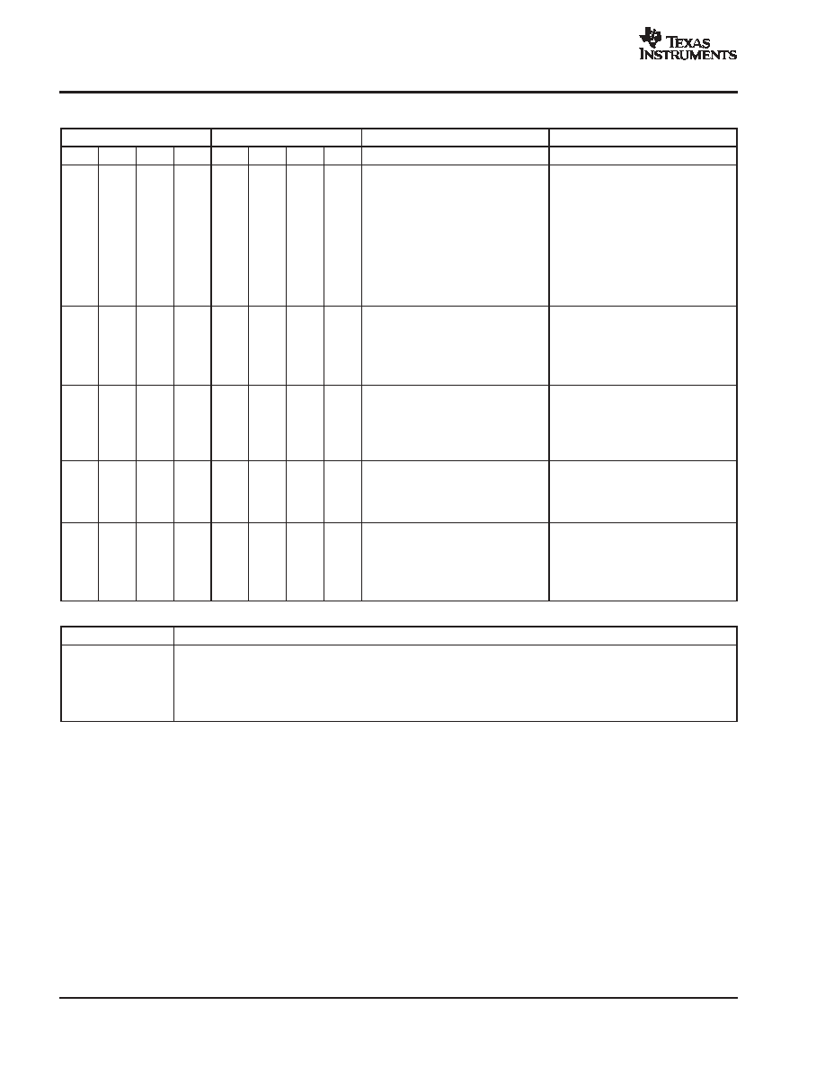
SERIAL INTERFACE TIMING
ADDRESS
DATA
DESCRIPTION
REMARKS
D7
D6
D5
D4
D3
D2
D1
D0
0
0
0
0
0. LVDS BUFFERS
0
0
Normal ADC Output
0
1
Deskew Pattern
Patterns Get Reversed in MSB First
Mode of LVDS
1
0
Sync Pattern
Patterns Get Reversed in MSB First
Mode of LVDS
1
1
Custom Pattern
Mode of LVDS
0
0
Output Current in LVDS = 3.5mA
0
1
Output Current in LVDS = 2.5mA
1
0
Output Current in LVDS = 4.5mA
1
1
Output Current in LVDS = 6.0mA
0
0
0
1
1. LSB/MSB MODE
D3
D2
D1
D0
Default LVDS Clock Output Current
0
X
X
1
2X LVDS Clock Output Current
0
0
X
X
LSB Mode
0
1
X
X
MSB Mode
0
0
1
0
2. POWER-DOWN ADC CHANNELS
D3
D2
D1
D0
X
X
X
X
Power-Down Channels 1 to 4; D3 is
for Channel 4 and D0 for Channel 1
Example: 1010 Powers Down
Channels 4 and 2 and Keeps
Channels 1 and 3 Alive
0
0
1
1
3. POWER-DOWN ADC CHANNELS
D3
D2
D1
D0
X
X
X
X
Power-Down Channels 5 to 8; D3 is
for Channel 8 and D0 for Channel 5
CUSTOM PATTERN (registers 4-6)
D3
D2
D1
D0
0
1
0
0
MSB
X
X
X
0
1
0
1
X
X
X
X
Bits for Custom Pattern
0
1
1
0
X
X
X
LSB
TEST PATTERNS(1)
Deskew
101010101010
Sync
000000111111
Custom
Any 12-bit pattern that is defined in the custom pattern registers 4 to 6. The output comes out in the following order:
D0(4) D1(4) D2(4) D3(4) D0(5) D1(5) D2(5) D3(5) D0(6) D1(6) D2(6) D3(6)
where, for example, D0(4) refers to the D0 bit of register 4, etc.
(1) Default is LSB first. If MSB is selected the above patterns will be reversed.

ADS5270
SBAS293D - JANUARY 2004 - REVISED MAY 2004
www.ti.com
7
LVDS TIMING DIAGRAM (PER ADC CHANNEL)
ADCLK
6X ADCLK
SERIAL DATA
1X ADCLK
LCLKP
LCLKN
OUTP
OUTN
ADCLKP
ADCLKN
Sample n data
Input
t
PROP
t
D
(A)
Sample n
Sample n+6
D3 D4 D5 D6 D7 D8 D9
D0 D1 D2
D0 D1 D2 D3 D4 D5 D6 D7 D8 D9
D11
D10
1
t
SAMPLE
t
S
2
D11
D10
D1
D0
6.5 Clock Cycles
RESET TIMING
0V
+AVDD
0V
+AVDD
Power
Supply
RESET
t
1
t
2
t
1
> 10ms
t
2
> 100ns
POWER-DOWN TIMING
PD
Device Fully
Powers Down
Device Fully
Powers Up
1
�
s
10
�
s
ADS5270
SBAS293D - JANUARY 2004 - REVISED MAY 2004
www.ti.com
8
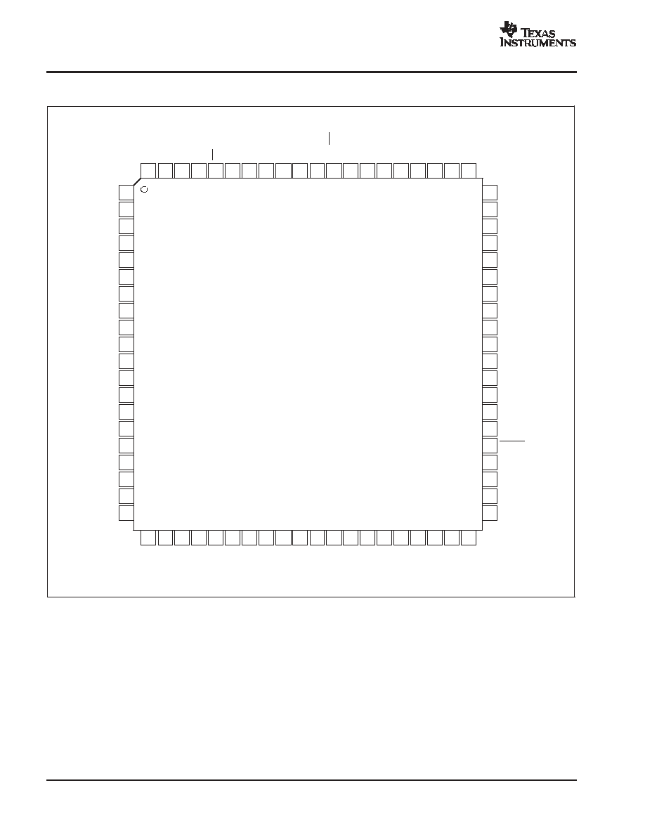
PIN CONFIGURATION
Top View
TQFP
60
59
58
57
56
55
54
53
52
51
50
49
48
47
46
45
44
43
42
41
AVDD
IN8
N
IN8
P
AVSS
IN7
N
IN7
P
AVDD
AVSS
IN6
N
IN6
P
AVSS
IN5
N
IN5
P
AVDD
LVSS
RESET
LVSS
LVSS
ADCLK
N
ADCLK
P
A
VSS
A
VSS
SC
L
K
SD
A
CS
AV
D
D
A
VSS
A
VSS
A
VSS
A
DCL
K
AV
D
D
IN
T
/
E
X
T
A
VSS
RE
F
T
RE
F
B
V
CM
IS
E
T
AV
D
D
A
VSS
A
VSS
OU
T1
P
OU
T
1
N
OU
T2
P
OU
T
2
N
LV
D
D
LV
S
S
OU
T3
P
OU
T
3
N
OU
T4
P
OU
T
4
N
OU
T5
P
OU
T
5
N
OU
T6
P
OU
T
6
N
LV
D
D
LV
S
S
OU
T7
P
OU
T
7
N
OU
T8
P
OU
T
8
N
1
2
3
4
5
6
7
8
9
10
11
12
13
14
15
16
17
18
19
20
AVDD
IN1
P
IN1
N
AVSS
IN2
P
IN2
N
AVDD
AVSS
IN3
P
IN3
N
AVSS
IN4
P
IN4
N
AVDD
LVSS
PD
LVSS
LVSS
LCLK
P
LCLK
N
80
79
78
77
76
75
74
73
72
71
70
21
22
23
24
25
26
27
28
29
30
31
69
32
33
34
35
36
37
38
39
40
68
67
66
65
64
63
62
61
ADS5270

ADS5270
SBAS293D - JANUARY 2004 - REVISED MAY 2004
www.ti.com
9
PIN DESCRIPTIONS
NAME
PIN #
NUMBER
OF PINS
I/O
DESCRIPTION
AVDD
1, 7, 14, 47, 54, 60, 63, 70, 75
9
I
Analog Power Supply
AVSS
4, 8, 11, 50, 53, 57, 61, 62, 68, 72-74, 79, 80
14
I
Analog Ground
LVDD
25, 35
2
I
LVDS Power Supply
LVSS
15, 17, 18, 26, 36, 43, 44, 46
8
I
LVDS Ground
IN1P
2
1
I
Channel 1 Differential Analog Input High
IN1N
3
1
I
Channel 1 Differential Analog Input Low
IN2P
5
1
I
Channel 2 Differential Analog Input High
IN2N
6
1
I
Channel 2 Differential Analog Input Low
IN3P
9
1
I
Channel 3 Differential Analog Input High
IN3N
10
1
I
Channel 3 Differential Analog Input Low
IN4P
12
1
I
Channel 4 Differential Analog Input High
IN4N
13
1
I
Channel 4 Differential Analog Input Low
IN5P
48
1
I
Channel 5 Differential Analog Input High
IN5N
49
1
I
Channel 5 Differential Analog Input Low
IN6P
51
1
I
Channel 6 Differential Analog Input High
IN6N
52
1
I
Channel 6 Differential Analog Input Low
IN7P
55
1
I
Channel 7 Differential Analog Input High
IN7N
56
1
I
Channel 7 Differential Analog Input Low
IN8P
58
1
I
Channel 8 Differential Analog Input High
IN8N
59
1
I
Channel 8 Differential Analog Input Low
REFT
67
1
I/O
Reference Top Voltage (0.1
�
F capacitor to ground)
REFB
66
1
I/O
Reference Bottom Voltage (0.1
�
F capacitor to ground)
VCM
65
1
O
Common-Mode Output Voltage
INT/EXT
69
1
I
Internal/External Reference Select; 0 = External, 1 = Internal
PD
16
1
I
Power-Down; 0 = Normal, 1 = Power-Down
LCLKP
19
1
O
Positive LVDS Clock
LCLKN
20
1
O
Negative LVDS Clock
ADCLK
71
1
I
Data Converter Clock Input
OUT1P
21
1
O
Channel 1 Positive LVDS Data Output
OUT1N
22
1
O
Channel 1 Negative LVDS Data Output
OUT2P
23
1
O
Channel 2 Positive LVDS Data Output
OUT2N
24
1
O
Channel 2 Negative LVDS Data Output
OUT3P
27
1
O
Channel 3 Positive LVDS Data Output
OUT3N
28
1
O
Channel 3 Negative LVDS Data Output
OUT4P
29
1
O
Channel 4 Positive LVDS Data Output
OUT4N
30
1
O
Channel 4 Negative LVDS Data Output
OUT5P
31
1
O
Channel 5 Positive LVDS Data Output
OUT5N
32
1
O
Channel 5 Negative LVDS Data Output
OUT6P
33
1
O
Channel 6 Positive LVDS Data Output
OUT6N
34
1
O
Channel 6 Negative LVDS Data Output
OUT7P
37
1
O
Channel 7 Positive LVDS Data Output
OUT7N
38
1
O
Channel 7 Negative LVDS Data Output
OUT8P
39
1
O
Channel 8 Positive LVDS Data Output
OUT8N
40
1
O
Channel 8 Negative LVDS Data Output
ADCLKP
41
1
O
Positive LVDS ADC Clock Output
ADCLKN
42
1
O
Negative LVDS ADC Clock Output
ISET
64
1
I/O
Bias Current Setting Resistor of 56k
to Ground
RESET
45
1
I
Reset to Default; 0 = Reset, 1 = Normal
CS
76
1
I
Chip Select; 0 = Select, 1 = No Select
SDA
77
1
I
Serial Data Input
SCLK
78
1
I
Serial Data Clock

ADS5270
SBAS293D - JANUARY 2004 - REVISED MAY 2004
www.ti.com
10
TYPICAL CHARACTERISTICS
Typical values are at TA = 25
�
C, clock frequency = maximum specified, 50% clock duty cycle, AVDD = 3.3V, LVDD = 3.3V, -1dBFS,
ISET = 56k
, internal voltage reference, and LVDS buffer current at 3.5mA per channel, unless otherwise noted.
SPECTRAL PERFORMANCE
A
m
pl
i
t
u
d
e
(
dB
)
Input Frequency (MHz)
0
-
20
-
40
-
60
-
80
-
100
-
120
0
15
5
10
20
f
IN
= 1MHz
SNR = 71.3dBFS
SINAD = 71.2dBFS
SFDR = 89.6dBc
SPECTRAL PERFORMANCE
A
m
pl
i
t
u
d
e
(
dB
)
Input Frequency (MHz)
0
-
20
-
40
-
60
-
80
-
100
-
120
0
10
15
5
20
f
IN
= 10MHz
SNR = 70.8dBFS
SINAD = 70.5dBFS
SFDR = 85.4dBc
INTERMODULATION DISTORTION
A
m
pl
i
t
u
d
e
(
dB
)
Input Frequency (MHz)
0
-
20
-
40
-
60
-
80
-
100
-
120
0
15
5
10
20
F1 = 9.5MHz (
-
7dBFS)
F2 = 10.2MHz (
-
7dBFS)
IMD (3) =
-
85dBFS
SPECTRAL PERFORMANCE
A
m
pl
i
t
u
d
e
(
dB
)
Input Frequency (MHz)
0
-
20
-
40
-
60
-
80
-
100
-
120
0
15
5
10
20
f
IN
= 5MHz (
-
1dBFS)
SNR = 70.4dBFS
SINAD = 70.2dBFS
SFDR = 87.2dBc
SPECTRAL PERFORMANCE
A
m
pl
i
t
u
d
e
(
dB
)
Input Frequency (MHz)
0
-
20
-
40
-
60
-
80
-
100
-
120
0
15
5
10
20
f
IN
= 20MHz
SNR = 70.5dBFS
SINAD = 70.2dBFS
SFDR = 83.4dBc
DIFFERENTIAL NONLINEARITY
DNL
(
L
S
B
)
Code
1.0
0.8
0.6
0.4
0.2
0
-
0.2
-
0.4
-
0.6
-
0.8
-
1.0
0
1536
2048
2560
3072
3584
512
1024
4096
f
IN
= 5MHz

ADS5270
SBAS293D - JANUARY 2004 - REVISED MAY 2004
www.ti.com
11
TYPICAL CHARACTERISTICS (continued)
Typical values are at TA = 25
�
C, clock frequency = maximum specified, 50% clock duty cycle, AVDD = 3.3V, LVDD = 3.3V, -1dBFS,
ISET = 56k
, internal voltage reference, and LVDS buffer current at 3.5mA per channel, unless otherwise noted.
INTEGRAL NONLINEARITY
INL
(
LS
B
)
Code
2.0
1.5
1.0
0.5
0
-
0.5
-
1.0
-
1.5
-
2.0
0
1536
2048
2560
3072
3584
512
1024
4096
f
IN
= 5MHz
SWEPT INPUT POWER
S
N
R
(
dB
c
,
dB
F
S
)
Input Amplitude (A)
100
90
80
70
60
50
40
30
20
10
0
-
70
-
60
-
30
-
20
-
10
-
50
-
40
0
f
IN
= 10MHz
SNR (dBFS)
SNR (dBc)
SFDR (dBc)
DYNAMIC PERFORMANCE vs INPUT FREQUENCY
S
F
DR,
S
N
R
(
d
B
F
S
)
Input Frequency (MHz)
95
90
85
80
75
70
65
60
55
5
20
25
30
35
40
45
10
15
50
SFDR
SNR
SWEPT INPUT POWER
S
N
R
(
dB
c
,
dB
F
S
)
Input Amplitude (A)
100
90
80
70
60
50
40
30
20
10
0
-
70
-
60
-
30
-
20
-
10
-
50
-
40
0
f
IN
= 5MHz
SNR (dBFS)
SNR (dBc)
SFDR (dBc)
DYNAMIC PERFORMANCE vs DUTY CYCLE
S
F
DR,
S
N
R
(
d
B
F
S
)
Duty Cycle (%)
90
85
80
75
70
65
60
55
20
50
60
70
30
40
80
f
IN
= 5MHz
SFDR
SNR
DYNAMIC PERFORMANCE vs CLOCK FREQUENCY
S
F
DR,
S
NR,
S
I
NA
D
(
d
B
F
S
)
Clock Frequency (MHz)
90
85
80
75
70
65
60
55
20
35
40
25
30
45
SFDR
SNR
SINAD
f
IN
= 5MHz

ADS5270
SBAS293D - JANUARY 2004 - REVISED MAY 2004
www.ti.com
12
TYPICAL CHARACTERISTICS (continued)
Typical values are at TA = 25
�
C, clock frequency = maximum specified, 50% clock duty cycle, AVDD = 3.3V, LVDD = 3.3V, -1dBFS,
ISET = 56k
, internal voltage reference, and LVDS buffer current at 3.5mA per channel, unless otherwise noted.
DYNAMIC PERFORMANCE vs CLOCK FREQUENCY
S
F
DR,
S
NR,
S
I
NA
D
(
d
B
F
S
)
Clock Frequency (MHz)
95
90
85
80
75
70
65
60
55
20
35
40
25
30
45
SFDR
SNR
SINAD
f
IN
= 10MHz
IAV
DD
, IDV
DD
vs CLOCK FREQUENCY
IA
V
DD
,I
D
V
DD
(m
A
)
Clock Frequency (MHz)
0.30
0.25
0.20
0.15
0.10
0.05
0
20
35
40
25
30
45
IAV
DD
IDV
DD
f
IN
= 5MHz
POWER DISSIPATION vs TEMPERATURE
P
o
w
e
r
D
i
s
s
i
pa
t
i
on
(
m
W
)
Temperature ( C)
904
902
900
898
896
894
892
890
888
886
-
40
35
60
-
15
10
85
f
IN
= 5MHz
ADS5270
SBAS293D - JANUARY 2004 - REVISED MAY 2004
www.ti.com
13
THEORY OF OPERATION
OVERVIEW
The ADS5270 is an 8-channel, high-speed, CMOS ADC.
It consists of a high-performance sample-and-hold circuit
at the input, followed by a 12-bit ADC. The 12 bits given out
by each channel are serialized and sent out on a single pair
of pins in LVDS format. All eight channels of the ADS5270
operate from a single clock referred to as ADCLK. The
sampling clocks for each of the eight channels are
generated from the input clock using a carefully matched
clock buffer tree. The 12X clock required for the serializer
is generated internally from ADCLK using a phase lock
loop (PLL). A 6X and a 1X clock are also output in LVDS
format along with the data to enable easy data capture.
The ADS5270 operates from internally generated
reference voltages that are trimmed to ensure matching
across multiple devices on a board. This feature eliminates
the need for external routing of reference lines and also
improves matching of the gain across devices. The
nominal values of REF
T
and REF
B
are 2V and 1V,
respectively. These values imply that a differential input of
-1V corresponds to the zero code of the ADC, and a
differential input of +1V corresponds to the full-scale code
(4095 LSB). V
CM
(common-mode voltage of REF
P
and
REF
N
) is also made available externally through a pin, and
is nominally 1.5V.
The ADC employs a pipelined converter architecture
consisting of a combination of multi-bit and single-bit
internal stages. Each stage feeds its data into the digital
error correction logic, ensuring excellent differential
linearity and no missing codes at the 12-bit level. The
pipeline architecture results in a data latency of 6.5 clock
cycles.
The output of the ADC goes to a serializer that operates
from a 12X clock generated by the PLL. The 12 data bits
from each channel are serialized and sent LSB first. In
addition to serializing the data, the serializer also
generates a 1X clock and a 6X clock. These clocks are
generated in the same way the serialized data is
generated, so these clocks maintain perfect synchroniza-
tion with the data. The data and clock outputs of the
serializer are buffered externally using LVDS buffers.
Using LVDS buffers to transmit data externally has
multiple advantages, such as reduced number of output
pins (saving routing space on the board), reduced power
consumption, and reduced effects of digital noise coupling
to the analog circuit inside the ADS5270.
The ADS5270 operates from two sets of supplies and
grounds. The analog supply/ground set is denoted as
AVDD/AVSS, while the digital set is denoted by
LVDD/LVSS.
DRIVING THE ANALOG INPUTS
The analog input biasing is shown in Figure 1. The
recommended method to drive the inputs is through AC
coupling. AC coupling removes the worry of setting the
common-mode of the driving circuit, since the inputs are
biased internally using two 600
resistors.
CM Buffer 2
CM Buffer 1
Internal
Voltage
Reference
Input
Circuitry
IN+
IN
-
V
CM
600
600
ADS5270
Figure 1. Analog Input Bias Circuitry
The sampling capacitor used to sample the inputs is 4pF.
The choice of the external AC coupling capacitor is
dictated by the attenuation at the lowest desired input
frequency of operation. The attenuation resulting from
using a 10nF AC coupling capacitor is 0.04%.
If the input is DC-coupled, then the output common-mode
voltage of the circuit driving the ADS5270 should match
the V
CM
(which is provided as an output pin) to within
�
50mV. It is recommended that the output common-mode
of the driving circuit be derived from V
CM
provided by the
device.

ADS5270
SBAS293D - JANUARY 2004 - REVISED MAY 2004
www.ti.com
14
The sampling circuit consists of a low-pass RC filter at the
input to filter out noise components that might be getting
differentially coupled on the input pins. The inputs are
sampled on two 4pF capacitors. The sampling on the
capacitors is done with respect to an internally generated
common-mode voltage (INCM). The switches connecting
the sampling capacitors to the INCM are opened out first
(before the switches connecting them to the analog
inputs). This ensures that the charge injection arising out
of the switches opening is independent of the input signal
amplitude to a first-order of approximation. SP refers to a
sampling clock whose falling edge comes an instant
before the SAMPLE clock. The falling edge of SP
determines the sampling instant.
15
IN
-
1.5pF
SP
SP
SP
(defines sampling instant)
INCM
(internally generated voltage)
INCM
4pF
Sample
15
IN+
1.5pF
1.7pF
4pF
Sample
Figure 2. Input Circuitry
INPUT OVER-VOLTAGE RECOVERY
The differential full-scale input peak-to-peak supported by
the ADS5270 is 2V. For a nominal value of V
CM
(1.5V), IN
P
and IN
N
can swing from 1V to 2V. The ADS5270 is
specially designed to handle an over-voltage differential
peak-to-peak voltage of 4V (2.5V and 0.5V swings on IN
P
and IN
N
). If the input common-mode is not considerably off
from V
CM
during overload (less than 300mV), recovery
from an over-voltage input condition is expected to be
within 4 clock cycles. All of the amplifiers in the SHA and
ADC are specially designed for excellent recovery from an
overload signal.
REFERENCE CIRCUIT DESIGN
The digital beam-forming algorithm relies heavily on gain
matching across all receiver channels. A typical system
would have about 12 octal ADCs on the board. In such a
case, it is critical to ensure that the gain is matched,
essentially requiring the reference voltages seen by all the
ADCs to be the same. Matching references within the eight
channels of a chip is done by using a single internal
reference voltage buffer. Trimming the reference voltages
on each chip during production ensures the reference
voltages are well matched across different chips.
All bias currents required for the internal operation of the
device are set using an external resistor to ground at pin
ISET. Using a 56k
resistor on ISET generates an internal
reference current of 20
�
A. This current is mirrored
internally to generate the bias current for the internal
blocks. Using a larger external resistor at ISET reduces the
reference bias current and thereby scales down the device
operating power. However, it is recommended that the
external resistor be within 10% of the specified value of
56k so that the internal bias margins for the various blocks
are proper.
Buffering the internal bandgap voltage also generates a
voltage called V
CM
, which is set to the midlevel of REF
T
and REF
B
, and is accessible on a pin. The internal buffer
driving V
CM
has a drive of
�
2mA. It is meant as a reference
voltage to derive the input common-mode in case the input
is directly coupled.
When using the internal reference mode, a resistor greater
than 2
should be added between the reference pins
(REF
T
and REF
B
) and the decoupling capacitor, as shown
in Figure 3.
REF
T
REF
B
0.1
�
F
2.2
�
F
> 2
> 2
2.2
�
F
0.1
�
F
ADS5270
Figure 3. Internal Refernce Mode
The device also supports the use of external reference
voltages. This mode involves forcing REF
T
and REF
B
externally. In this mode, the internal reference buffer is
tri-stated. Since the switching current for the eight ADCs
come from the externally forced references, it is possible
for the performance to be slightly less than when the
internal references are used. It should be noted that in this
mode, V
CM
and ISET continue to be generated from the
internal bandgap voltage, as in the internal reference
mode. It is therefore important to ensure that the
common-mode voltage of the externally forced reference
voltages matches to within 50mV of V
CM
.
CLOCKING
The eight channels on the chip run off a single ADCLK
input. To ensure that the aperture delay and jitter are same
for all the channels, a clock tree network is used to
generate individual sampling clocks to each channel. The

ADS5270
SBAS293D - JANUARY 2004 - REVISED MAY 2004
www.ti.com
15
clock paths for all the channels are matched from the
source point all the way to the sample-and-hold. This
ensures that the performance and timing for all the
channels are identical. The use of the clock tree for
matching introduces an aperture delay, which is defined as
the delay between the rising edge of ADCLK and the actual
instant of sampling. The aperture delays for all the
channels are matched, and vary between 2.5ns to 4.5ns
across devices. Another critical spec is the aperture jitter
that is defined as the uncertainty of the sampling instant.
The gates in the clock path are designed so as to give an
rms jitter of about 1ps.
The input ADCLK should ideally have a 50% duty cycle.
However, while routing ADCLK to different components on
board, the duty cycle of the ADCLK reaching the ADS5270
could deviate from 50%. A smaller (or larger) duty cycle
eats into the time available for sample or hold phases of
each circuit, and is therefore not optimal. For this reason,
the internal PLL is used to generate an internal clock that
has 50% duty cycle.
The use of the PLL automatically dictates the lower
frequency of operation to be about 20MHz.
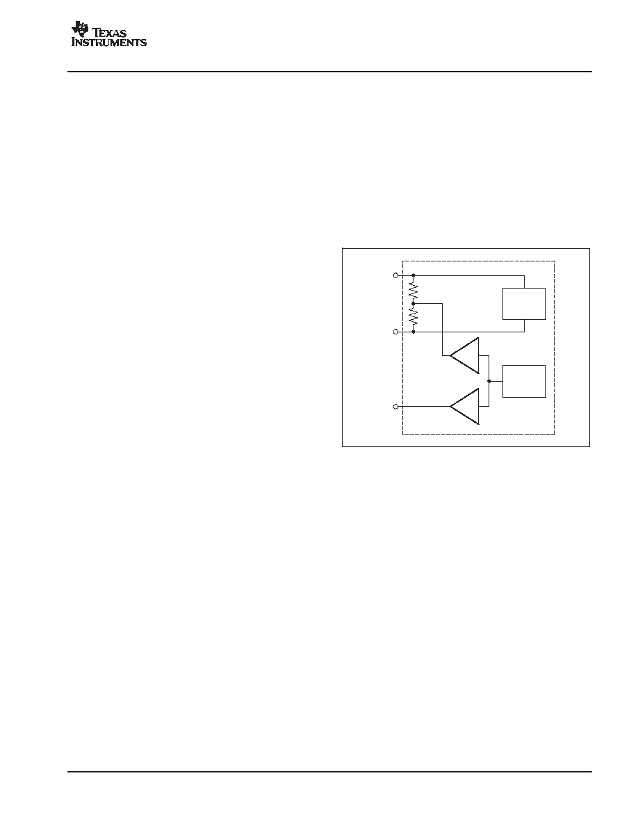
LVDS BUFFERS
The LVDS buffer has two current sources, as shown in
Figure 4. OUT
P
and OUT
N
are loaded externally by a
resistive load that is ideally about 100
. Depending on the
data being 0 or 1, the currents are directed in one or the
other direction through the resistor. The LVDS buffer has
four current settings. The default current setting is 3.5mA,
and gives a differential drop of about
�
350mV across the
100
resistor.
External
Termination
Resistor
OUT
P
High
Low
OUT
N
Low
High
Figure 4. LVDS Buffer
The LVDS buffer gets data from a serializer that takes the
output data from each channel and serializes it into a
single data stream. For a clock frequency of 40MHz, the
data rate output by the serializer is 480 MBPS. The data
comes out LSB first, with a register programmability to
revert to MSB first. The serializer also gives out a 1X clock
and a 6X clock. The 6X clock (denoted as LCLK
P
/ LCLK
N
)
is meant to synchronize the capture of the LVDS data. The
deskew mode can be enabled as well, using a register
setting. This mode gives out a data stream of alternate 0s
and 1s and can be used determine the relative delay
between the 6X clock and the output data for optimum
capture. A 1X clock is also generated by the serializer and
transmitted by the LVDS buffer. The 1X clock (referred to
as ADCLK
P
/ADCLK
N
) is used to determine the start of the
12-bit data frame. The sync mode (enabled through a
register setting) gives out a data of six 0s followed by six
1s. Using this mode, the 1X clock can be used to determine
the start of the data frame. In addition to the deskew mode
pattern and the sync pattern, a custom pattern can be
defined by the user and output from the LVDS buffer.
NOISE COUPLING ISSUES
High-speed mixed signals are sensitive to various types of
noise coupling. One of the main sources of noise is the
switching noise from the serializer and the output buffers.
Maximum care is taken to isolate these noise sources from
the sensitive analog blocks. As a starting point, the analog
and digital domains of the chip are clearly demarcated.
AVDD and AVSS are used to denote the supplies for the
analog sections, while LVDD and LVSS are used to denote
the digital supplies. Care is taken to ensure that there is
minimal interaction between the supply sets within the
device. The extent of noise coupled and transmitted from
the digital to the analog sections depends on the following:
1.
The effective inductances of each of the supply/ground
sets.
2.
The isolation between the digital and analog
supply/ground sets.
Smaller effective inductance of the supply/ground pins
leads to better suppression of the noise. For this reason,
multiple pins are used to drive each supply/ground. It is
also critical to ensure that the impedances of the supply
and ground lines on board are kept to the minimum
possible values. Use of ground planes in the board as well
as large decoupling capacitors between the supply and
ground lines are necessary to get the best possible SNR
from the device.
It is recommended that the isolation be maintained on
board by using separate supplies to drive AVDD and
LVDD, as well as separate ground planes for AVSS and
LVSS.
The use of LVDS buffers reduces the injected noise
considerably, compared to CMOS buffers. The current in
the LVDS buffer is independent of the direction of
switching. Also, the low output swing as well as the
differential nature of the LVDS buffer results in low-noise
coupling.

ADS5270
SBAS293D - JANUARY 2004 - REVISED MAY 2004
www.ti.com
16
POWER-DOWN MODE
The ADS5270 has a power-down pin, PD. Pulling PD high
causes the devices to enter the power-down mode. In this
mode, the reference and clock circuitry as well as all the
channels are powered down. Device power consumption
drops to less than 100mW in this mode. Individual
channels can also be selectively powered down by
programming registers.
The ADS5270 also has an internal circuit that monitors the
state of stopped clocks. If ADCLK is stopped (or if it runs
at a speed < 3MHz), this monitoring circuit generates a
logic signal that puts the device in a power-down state. As
a result, the power consumption of the device goes to less
than 100mW when ADCLK is stopped. This circuit can
also be disabled using register options.
SUPPLY SEQUENCE
The following supply sequence is recommended for
powering up the device:
1.
AVDD is powered up.
2.
LVDD is powered up.
After the supplies have stabilized, it is required to give the
device an active RESET pulse. This results in all internal
registers getting reset to their default value of 0 (inactive).
Without RESET, it is possible that some registers might be
in their non-default state on power-up. This could cause
the device to malfunction.
LAYOUT OF PCB WITH
POWERPAD THERMALLY
ENHANCED PACKAGES
The ADS5270 is housed in an 80-lead PowerPAD
thermally enhanced package. To make optimum use of the
thermal efficiencies designed into the PowerPAD
package, the PCB must be designed with this technology
in mind. Please refer to SLMA004 PowerPAD brief
PowerPAD Made Easy (refer to our web site at
www.ti.com), which addresses the specific considerations
required when integrating a PowerPAD package into a
PCB design. For more detailed information, including
thermal modeling and repair procedures, please see
SLMA002 technical brief PowerPAD Thermally Enhanced
Package (www.ti.com).


IMPORTANT NOTICE
Texas Instruments Incorporated and its subsidiaries (TI) reserve the right to make corrections, modifications,
enhancements, improvements, and other changes to its products and services at any time and to discontinue
any product or service without notice. Customers should obtain the latest relevant information before placing
orders and should verify that such information is current and complete. All products are sold subject to TI's terms
and conditions of sale supplied at the time of order acknowledgment.
TI warrants performance of its hardware products to the specifications applicable at the time of sale in
accordance with TI's standard warranty. Testing and other quality control techniques are used to the extent TI
deems necessary to support this warranty. Except where mandated by government requirements, testing of all
parameters of each product is not necessarily performed.
TI assumes no liability for applications assistance or customer product design. Customers are responsible for
their products and applications using TI components. To minimize the risks associated with customer products
and applications, customers should provide adequate design and operating safeguards.
TI does not warrant or represent that any license, either express or implied, is granted under any TI patent right,
copyright, mask work right, or other TI intellectual property right relating to any combination, machine, or process
in which TI products or services are used. Information published by TI regarding third-party products or services
does not constitute a license from TI to use such products or services or a warranty or endorsement thereof.
Use of such information may require a license from a third party under the patents or other intellectual property
of the third party, or a license from TI under the patents or other intellectual property of TI.
Reproduction of information in TI data books or data sheets is permissible only if reproduction is without
alteration and is accompanied by all associated warranties, conditions, limitations, and notices. Reproduction
of this information with alteration is an unfair and deceptive business practice. TI is not responsible or liable for
such altered documentation.
Resale of TI products or services with statements different from or beyond the parameters stated by TI for that
product or service voids all express and any implied warranties for the associated TI product or service and
is an unfair and deceptive business practice. TI is not responsible or liable for any such statements.
Following are URLs where you can obtain information on other Texas Instruments products and application
solutions:
Products
Applications
Amplifiers
amplifier.ti.com
Audio
www.ti.com/audio
Data Converters
dataconverter.ti.com
Automotive
www.ti.com/automotive
DSP
dsp.ti.com
Broadband
www.ti.com/broadband
Interface
interface.ti.com
Digital Control
www.ti.com/digitalcontrol
Logic
logic.ti.com
Military
www.ti.com/military
Power Mgmt
power.ti.com
Optical Networking
www.ti.com/opticalnetwork
Microcontrollers
microcontroller.ti.com
Security
www.ti.com/security
Telephony
www.ti.com/telephony
Video & Imaging
www.ti.com/video
Wireless
www.ti.com/wireless
Mailing Address:
Texas Instruments
Post Office Box 655303 Dallas, Texas 75265
Copyright
2004, Texas Instruments Incorporated