 | –≠–ª–µ–∫—Ç—Ä–æ–Ω–Ω—ã–π –∫–æ–º–ø–æ–Ω–µ–Ω—Ç: OPA682N | –°–∫–∞—á–∞—Ç—å:  PDF PDF  ZIP ZIP |
nternational Airport Industrial Park ∑ Mailing Address: PO Box 11400, Tucson, AZ 85734 ∑ Street Address: 6730 S. Tucson Blvd., Tucson, AZ 85706 ∑ Tel: (520) 746-1111
Twx: 910-952-1111 ∑ Internet: http://www.burr-brown.com/ ∑ Cable: BBRCORP ∑ Telex: 066-6491 ∑ FAX: (520) 889-1510 ∑ Immediate Product Info: (800) 548-6132
Wideband, Fixed Gain
BUFFER AMPLIFIER With Disable
OPA682
Æ
FEATURES
q
INTERNALLY FIXED GAIN: +2 OR
±
1
q
HIGH BANDWIDTH (G = +2): 240MHz
q
LOW SUPPLY CURRENT: 6mA
q
LOW DISABLED CURRENT: 320
µ
A
q
HIGH OUTPUT CURRENT: 150mA
q
OUTPUT VOLTAGE SWING:
±
4.0V
q
±
5V OR SINGLE +5V OPERATION
q
SOT23-6 AVAILABLE
APPLICATIONS
q
BROADBAND VIDEO LINE DRIVERS
q
VIDEO MULTIPLEXERS
q
MULTIPLE LINE VIDEO DA
q
PORTABLE INSTRUMENTS
q
ADC BUFFERS
q
ACTIVE FILTERS
TM
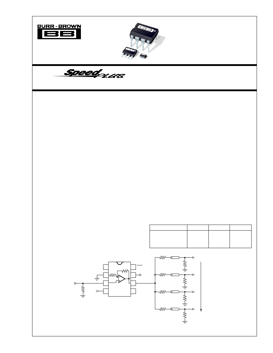
DESCRIPTION
The OPA682 provides an easy to use, broadband fixed gain
buffer amplifier. Depending on the external connections, the
internal resistor network may be used to provide either a
fixed gain of +2 video buffer or a gain of +1 or ≠1 voltage
buffer. Operating on a very low 6mA supply current, the
OPA682 offers a slew rate and output power normally
associated with a much higher supply current. A new output
stage architecture delivers high output current with a mini-
mal headroom and crossover distortion. This gives excep-
tional single supply operation. Using a single +5V supply,
the OPA682 can deliver a 1V to 4V output swing with over
100mA drive current and 200MHz bandwidth. This combi-
nation of features makes the OPA682 an ideal RGB line
driver or single supply ADC input driver.
OPA682 RELATED PRODUCTS
SINGLES
DUALS
TRIPLES
Voltage Feedback
OPA680
OPA2680
OPA3680
Current Feedback
OPA681
OPA2681
OPA3681
Fixed Gain
OPA682
OPA2682
OPA3682
The OPA682's low 6mA supply current is precisely trimmed
at 25
∞
C. This trim, along with low drift over temperature,
guarantees lower maximum supply current than competing
products that report only a room temperature nominal supply
current. System power may be further reduced by using the
optional disable control pin. Leaving this disable pin open, or
holding it high, gives normal operation. If pulled low, the
OPA682 supply current drops to less than 320
µ
A while the
output goes into a high impedance state. This feature may be
used for either power savings or for video MUX applications.
OPA682
OPA682
OPA682
©
1999 Burr-Brown Corporation
PDS-1428C
Printed in U.S.A. September, 1999
Video
Out
75
75
RG-59
75
75
RG-59
75
75
RG-59
75
75
RG-59
75
1
2
3
4
8
7
6
5
DIS
OPA682
8-Pin DIP, SO-8
G = +2
240MHz, 4-Output Component Video D/A
+5V
≠5V
Video
In
2
Æ
OPA682
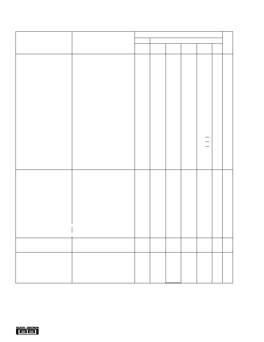
SPECIFICATIONS: V
S
=
±
5V
G = +2 (≠IN grounded) and R
L
= 100
(Figure 1 for AC performance only), unless otherwise noted.
OPA682P, U, N
TYP
GUARANTEED
(1)
0
∞
C to
≠40
∞
C to
MIN/
TEST
PARAMETER
CONDITIONS
+25
∞
C
+25
∞
C
70
∞
C
+85
∞
C
UNITS
MAX
LEVEL
(2 )
AC PERFORMANCE (Figure 1)
Small-Signal Bandwidth (V
O
< 0.5Vp-p)
G = +1
330
MHz
typ
C
G = +2
240
220
210
190
MHz
min
B
G = ≠1
220
MHz
typ
C
Bandwidth for 0.1dB Gain Flatness
G = +2, V
O
< 0.5Vp-p
150
50
45
45
MHz
min
B
Peaking at a Gain of +1
V
O
< 0.5Vp-p
0.8
2
4
dB
max
B
Large-Signal Bandwidth
G = +2, V
O
= 5Vp-p
210
MHz
typ
C
Slew Rate
G = +2, 4V Step
2100
1600
1600
1200
V/
µ
s
min
B
Rise/Fall Time
G = +2, V
O
= 0.5V Step
1.7
ns
typ
C
G = +2, V
O
= 5V Step
2.0
ns
typ
C
Settling Time to 0.02%
G = +2, V
O
= 2V Step
12
ns
typ
C
0.1%
G = +2, V
O
= 2V Step
8
ns
typ
C
Harmonic Distortion
G = +2, f = 5MHz, V
O
= 2Vp-p
2nd Harmonic
R
L
= 100
≠69
≠62
≠59
≠57
dBc
max
B
R
L
500
≠79
≠70
≠67
≠65
dBc
max
B
3rd Harmonic
R
L
= 100
≠84
≠75
≠71
≠69
dBc
max
B
R
L
500
≠95
≠82
≠76
≠74
dBc
max
B
Input Voltage Noise
f > 1MHz
2.2
3.0
3.4
3.6
nV/
Hz
max
B
Non-Inverting Input Current Noise
f > 1MHz
12
14
15
15
pA/
Hz
max
B
Inverting Input Current Noise
f > 1MHz
15
18
18
19
pA/
Hz
max
B
Differential Gain
NTSC, R
L
= 150
0.001
%
typ
C
NTSC, R
L
= 37.5
0.008
%
typ
C
Differential Phase
NTSC, R
L
= 150
0.01
deg
typ
C
NTSC, R
L
= 37.5
0.05
deg
typ
C
DC PERFORMANCE
(3)
Gain Error
G = +1
±
0.2
%
typ
C
G = +2
±
0.3
±
1.5
%
max
A
G = ≠1
±
0.2
±
1.5
%
max
B
Internal R
F
and R
G
Maximum
400
480
510
520
max
A
Minimum
400
320
310
290
min
A
Average Drift
0.13
0.13
0.13
%/C
∞
max
B
Input Offset Voltage
V
CM
= 0V
±
1.3
±
5
±
6.5
±
7.5
mV
max
A
Average Offset Voltage Drift
V
CM
= 0V
+35
+40
µ
V/
∞
C
max
B
Non-Inverting Input Bias Current
V
CM
= 0V
+30
+55
±
65
±
85
µ
A
max
A
Average Non-Inverting Input Bias Current Drift
V
CM
= 0V
≠400
≠450
nA/
∞
C
max
B
Inverting Input Bias Current
V
CM
= 0V
±
10
±
40
±
50
±
55
µ
A
max
A
Average Inverting Input Bias Current Drift
V
CM
= 0V
≠125
≠150
nA
∞
C
max
B
INPUT
Common-Mode Input Range
±
3.5
±
3.4
±
3.3
±
3.2
V
min
A
Non-Inverting Input Impedance
100 || 2
k
|| pF
typ
C
OUTPUT
Voltage Output Swing
No Load
±
4.0
±
3.8
±
3.7
±
3.6
V
min
A
100
Load
±
3.9
±
3.7
±
3.6
±
3.3
V
min
A
Current Output, Sourcing
+190
+160
+140
+80
mA
min
A
Sinking
≠150
≠135
≠130
≠80
mA
min
A
Closed-Loop Output Impedance
G = +2, f = 100kHz
0.03
typ
C
The information provided herein is believed to be reliable; however, BURR-BROWN assumes no responsibility for inaccuracies or omissions. BURR-BROWN
assumes no responsibility for the use of this information, and all use of such information shall be entirely at the user's own risk. Prices and specifications are subject
to change without notice. No patent rights or licenses to any of the circuits described herein are implied or granted to any third party. BURR-BROWN does not
authorize or warrant any BURR-BROWN product for use in life support devices and/or systems.
3
Æ
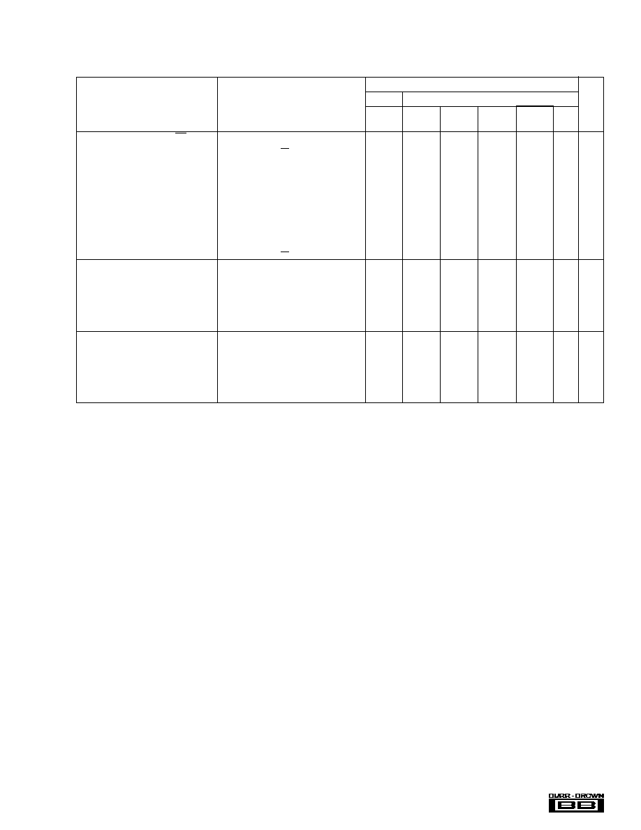
OPA682
SPECIFICATIONS: V
S
=
±
5V
(Cont.)
G = +2 (≠IN grounded) and R
L
= 100
(Figure 1 for AC performance only), unless otherwise noted.
OPA682P, U, N
TYP
GUARANTEED
(1)
0
∞
C to
≠40
∞
C to
MIN/
TEST
PARAMETER
CONDITIONS
+25
∞
C
+25
∞
C
70
∞
C
+85
∞
C
UNITS
MAX
LEVEL
(2)
DISABLE/POWER DOWN (DIS Pin)
Power Down Supply Current (+V
S
)
V
DIS
= 0
≠320
µ
A
typ
C
Disable Time
100
ns
typ
C
Enable Time
25
ns
typ
C
Off Isolation
G = +2, 5MHz
70
dB
typ
C
Output Capacitance in Disable
4
pF
typ
C
Turn On Glitch
G = +2, R
L
= 150
±
50
mV
typ
C
Turn Off Glitch
G = +2, R
L
= 150
±
20
mV
typ
C
Enable Voltage
3.3
3.5
3.6
3.7
V
min
A
Disable Voltage
1.8
1.7
1.6
1.5
V
max
A
Control Pin Input Bias Current
V
DIS
= 0
100
160
160
160
µ
A
max
A
POWER SUPPLY
Specified Operating Voltage
±
5
V
typ
C
Maximum Operating Voltage Range
±
6
±
6
±
6
V
max
A
Max Quiescent Current
V
S
=
±
5V
6
6.4
6.5
6.6
mA
max
A
Min Quiescent Current
V
S
=
±
5V
6
5.6
5.5
5.0
mA
min
A
Power Supply Rejection Ratio (≠PSRR)
Input Referred
58
52
50
49
dB
min
A
TEMPERATURE RANGE
Specification: P, U, N
≠40 to +85
∞
C
typ
C
Thermal Resistance,
JA
P
8-Pin DIP
100
∞
C/W
typ
C
U
SO-8
125
∞
C/W
typ
C
N
SOT23-6
150
∞
C/W
typ
C
NOTES: (1) Junction temperature = ambient temperature for low temperature limit and 25
∞
C guaranteed specifications. Junction temperature = ambient temperature
+23
∞
C at high temperature limit guaranteed specifications. (2) Test Levels: (A) 100% tested at 25
∞
C. Over temperature limits by characterization and simulation.
(B) Limits set by characterization and simulation. (C) Typical value only for information. (3) Current is considered positive out-of-node. V
CM
is the input common-
mode voltage.
4
Æ
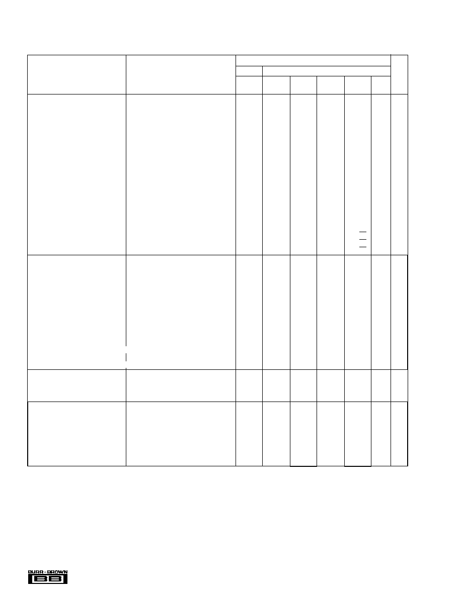
OPA682
SPECIFICATIONS: V
S
= +5V
G = +2 (≠IN grounded though 0.1
µ
F) and R
L
= 100
to V
S
/2 (Figure 2 for AC performance only), unless otherwise noted.
OPA682P, U, N
TYP
GUARANTEED
(1)
0
∞
C to
≠40
∞
C to
MIN/
TEST
PARAMETER
CONDITIONS
+25
∞
C
+25
∞
C
70
∞
C
+85
∞
C
UNITS
MAX
LEVEL
(2)
AC PERFORMANCE (Figure 2)
Small-Signal Bandwidth (V
O
< 0.5Vp-p)
G = +1
290
MHz
typ
C
G = +2
220
180
140
110
MHz
min
B
G = ≠1
200
MHz
typ
C
Bandwidth for 0.1dB Gain Flatness
G = +2, V
O
< 0.5Vp-p
100
50
35
23
MHz
min
B
Peaking at a Gain of +1
V
O
< 0.5Vp-p
0.4
2
4
dB
max
B
Large-Signal Bandwidth
G = +2, V
O
= 2Vp-p
210
MHz
typ
C
Slew Rate
G = +2, 2V Step
830
700
680
570
V/
µ
s
min
B
Rise/Fall Time
G = +2, V
O
= 0.5V Step
1.5
ns
typ
C
G = +2, V
O
= 2V Step
2.0
ns
typ
C
Settling Time to 0.02%
G = +2, V
O
= 2V Step
14
ns
typ
C
0.1%
G = +2, V
O
= 2V Step
9
ns
typ
C
Harmonic Distortion
G = +2, f = 5MHz, V
O
= 2Vp-p
2nd Harmonic
R
L
= 100
to V
S
/2
≠62
≠56
≠55
≠53
dBc
max
B
R
L
500
to V
S
/2
≠69
≠62
≠61
≠59
dBc
max
B
3rd Harmonic
R
L
= 100
to V
S
/2
≠71
≠64
≠63
≠61
dBc
max
B
R
L
500
to V
S
/2
≠73
≠68
≠67
≠65
dBc
max
B
Input Voltage Noise
f > 1MHz
2.2
3.0
3.4
3.6
nV/
Hz
max
B
Non-Inverting Input Current Noise
f > 1MHz
12
14
14
15
pA/
Hz
max
B
Inverting Input Current Noise
f > 1MHz
15
18
18
19
pA/
Hz
max
B
DC PERFORMANCE
(3)
Gain Error
G = +1
±
0.2
%
typ
C
G = +2
±
0.3
±
1.5
%
max
A
G = ≠1
±
0.2
±
1.5
%
max
B
Internal R
F
and R
G
Maximum
400
480
510
520
max
B
Minimum
400
320
310
290
min
B
Average Drift
0.13
0.13
0.13
%/C
∞
max
B
Input Offset Voltage
V
CM
= 2.5V
±
1
±
5
±
6
±
7
mV
max
A
Average Offset Voltage Drift
V
CM
= 2.5V
+15
+20
µ
V/
∞
C
max
B
Non-Inverting Input Bias Current
V
CM
= 2.5V
+40
+65
+75
+95
µ
A
max
A
Average Non-Inverting Input Bias Current Drift
V
CM
= 2.5V
≠300
≠350
nA/
∞
C
max
B
Inverting Input Bias Current
V
CM
= 2.5V
±
5
±
20
±
25
±
35
µ
A
max
A
Average Inverting Input Bias Current Drift
V
CM
= 2.5V
≠125
≠175
nA
∞
C
max
B
INPUT
Least Positive Input Voltage
1.5
1.6
1.7
1.8
V
max
B
Most Positive Input Voltage
3.5
3.4
3.3
3.2
V
min
B
Non-Inverting Input Impedance
100 || 2
k
|| pF
typ
C
OUTPUT
Most Positive Output Voltage
No Load
4.0
3.8
3.7
3.5
V
min
A
R
L
= 100
3.9
3.7
3.6
3.4
V
min
A
Least Positive Output Voltage
No Load
1.0
1.2
1.3
1.5
V
max
A
R
L
= 100
1.1
1.3
1.4
1.6
V
max
A
Current Output, Sourcing
+150
+110
+110
+60
mA
min
A
Sinking
≠110
≠75
≠70
≠50
mA
min
A
Output Impedance
G = +2, f = 100kHz
0.03
typ
C
5
Æ
OPA682
SPECIFICATIONS: V
S
= +5V
(Cont.)
G = +2 (≠IN grounded though 0.1
µ
F) and R
L
= 100
to V
S
/2 (Figure 2 for AC performance only), unless otherwise noted.
OPA682P, U, N
TYP
GUARANTEED
(1)
0
∞
C to
≠40
∞
C to
MIN/
TEST
PARAMETER
CONDITIONS
+25
∞
C
+25
∞
C
70
∞
C
+85
∞
C
UNITS
MAX
LEVEL
(2)
DISABLE/POWER DOWN (DIS Pin)
Power Down Supply Current (+V
S
)
V
DIS
= 0
≠270
µ
A
typ
C
Disable Time
100
ns
typ
C
Enable Time
25
ns
typ
C
Off Isolation
G = +2, 5MHz
65
dB
typ
C
Output Capacitance in Disable
4
pF
typ
C
Turn On Glitch
G = +2, R
L
= 150
, V
IN
= 2.5V
±
50
mV
typ
B
Turn Off Glitch
G = +2, R
L
= 150
, V
IN
= 2.5V
±
20
mV
typ
B
Enable Voltage
3.3
3.5
3.6
3.7
V
min
B
Disable Voltage
1.8
1.7
1.6
1.5
V
max
B
Control Pin Input Bias Current (DIS)
V
DIS
= 0
100
µ
A
typ
C
POWER SUPPLY
Specified Single Supply Operating Voltage
5
V
typ
C
Maximum Single Supply Operating Voltage
12
12
12
V
max
A
Max Quiescent Current
V
S
= +5V
4.8
5.3
5.4
5.4
mA
max
A
Min Quiescent Current
V
S
= +5V
4.8
4.1
3.7
3.6
mA
min
A
Power Supply Rejection Ratio (+PSRR)
Input Referred
50
dB
typ
C
TEMPERATURE RANGE
Specification: P, U, N
≠40 to +85
∞
C
typ
C
Thermal Resistance,
JA
P
8-Pin DIP
100
∞
C/W
typ
C
U
SO-8
125
∞
C/W
typ
C
N
SOT23-6
150
∞
C/W
typ
C
NOTES: (1) Junction temperature = ambient temperature for low temperature limit and 25
∞
C guaranteed specifications. Junction temperature = ambient temperature
+23
∞
C at high temperature limit guaranteed specifications. (2) Test Levels: (A) 100% tested at 25
∞
C. Over temperature limits by characterization and simulation.
(B) Limits set by characterization and simulation. (C) Typical value only for information. (3) Current is considered positive out-of-node. V
CM
is the input common-
mode voltage.