 | –≠–ª–µ–∫—Ç—Ä–æ–Ω–Ω—ã–π –∫–æ–º–ø–æ–Ω–µ–Ω—Ç: 12D12.075 | –°–∫–∞—á–∞—Ç—å:  PDF PDF  ZIP ZIP |
A
1.8 Watt Dual Series DC/DC Converters
Manufacturing Company, Inc. ∑ Concord, California 94520 ∑ Ph: 925/687-4411 or 800/542-3355 ∑ Fax: 925/687-3333 ∑ www.calex.com ∑ Email: sales@calex.com
1
eco# 041007-1
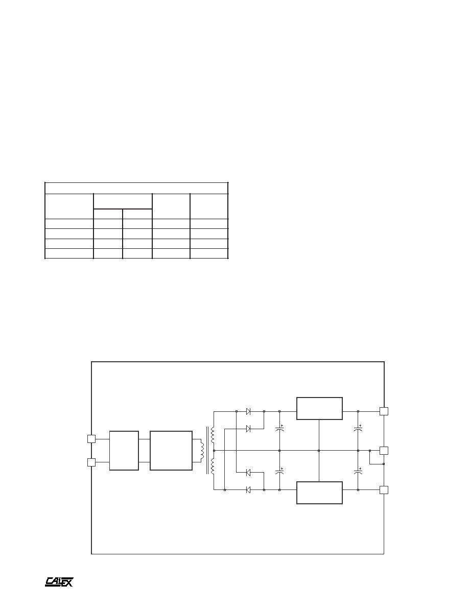
ISOLATION
TRANSFORMER
LC
INPUT
FILTER
BIPOLAR
PUSH-PULL
INVERTER
POSITIVE
REGULATOR
NEGATIVE
REGULATOR
1µF
10µF
3
4
5
1
2
+ INPUT
- INPUT
+ OUTPUT
CMN
- OUTPUT
SIX-SIDED SHIELDED STEEL CASE
BANDGAP REFERENCE
Features
Low Profile Case (0.375" High)
Low Noise Operation
"LC" Section Input Filter to Reduce Reflected Ripple
Wide Input Voltage Range
High Isolation Breakdown Voltage
(500 VDC Minimum)
Long Term Output Fault Survival
100% Burn-In, 100% Tested
5 Year Warranty
1.8 Watt Dual Series Block Diagram
Description
These 1.8 Watt Dual DC/DC Converters are designed for high
performance Industrial data acquisition systems and board
level products. The converter consists of a rugged bipolar
switching stage, isolation transformer, and high regulation
linear post regulator for low noise/highly stable DC outputs.
t
r
a
h
C
n
o
i
t
c
e
l
e
S
l
e
d
o
M
e
g
n
a
R
t
u
p
n
I
C
D
V
s
t
u
p
t
u
O
C
D
V
s
t
u
p
t
u
O
A
m
N
I
M
X
A
M
5
7
0
.
2
1
D
5
0
6
.
4
0
5
.
5
0
.
2
1
±
5
7
±
0
6
0
.
5
1
D
5
0
6
.
4
0
5
.
5
0
.
5
1
±
0
6
±
5
7
0
.
2
1
D
2
1
0
8
.
0
1
0
8
.
3
1
0
.
2
1
±
5
7
±
0
6
0
.
5
1
D
2
1
0
8
.
0
1
0
8
.
3
1
0
.
5
1
±
0
6
±
A
1.8 Watt Dual Series DC/DC Converters
Manufacturing Company, Inc. ∑ Concord, California 94520 ∑ Ph: 925/687-4411 or 800/542-3355 ∑ Fax: 925/687-3333 ∑ www.calex.com ∑ Email: sales@calex.com
2
eco# 041007-1
NOTES:
*
All parameters measured at Tc= 25∞ C, nominal input voltage
and full rated load unless otherwise noted. Refer to the
CALEX Application Notes for the definition of terms,
measurement circuits and other information.
(2)
Turn on time is defined as the time from the application of power
until the output is within 1% if its final value.
(3)
Determine the correct fuse size by calculating the maximum DC
current drain at low line input, maximum load (or use the supplied
curves) and then adding 20 to 25% to get the desired fuse size.
(4)
No minimum load required.
(5)
Short term stability is specified after a 30 minute warm-up at full
load and with constant line, load and ambient conditions.
(6)
The transient response is specified as the time required for the
output to settle from a 100% step load change (rise time of step
= 2µ Sec) to a 1% error band.
(7)
Dynamic response is the peak overshoot voltage during the
transient response as defined in note 6 above.
(8)
The functional temperature range is intended to give an additional
data point for use in evaluating this power supply. At the low
functional temperature the power supply will function with no
side effects, however sustained operation at the high functional
temperature will reduce expected operational life. The data
sheet specifications are not guaranteed over the functional
temperature range.
(9)
The case thermal impedance is specified as the case temperature
rise over ambient per package watt dissipated.
(10) Water Washability - Calex DC/DC converters are designed to
withstand most solder/wash processes. Careful attention should
be used when assessing the applicability in your specific
manufacturing process. Converters are not hermetically sealed.
*
s
r
e
t
e
m
a
r
a
P
t
u
p
n
I
l
e
d
o
M
0
6
0
.
5
1
D
5
5
7
0
.
2
1
D
5
0
6
0
.
5
1
D
2
1
5
7
0
.
2
1
D
2
1
s
t
i
n
U
e
g
n
a
R
e
g
a
t
l
o
V
N
I
M
X
A
M
0
6
.
4
0
5
.
5
0
8
.
0
1
0
8
.
3
1
C
D
V
w
b
z
H
M
0
2
-
0
,
e
l
p
p
i
R
d
e
t
c
e
l
f
e
R
P
Y
T
X
A
M
0
0
1
0
0
2
0
8
0
5
1
P
-
P
A
m
d
a
o
L
ll
u
F
t
n
e
r
r
u
C
t
u
p
n
I
d
a
o
L
o
N
P
Y
T
P
Y
T
0
5
6
0
3
1
5
6
2
5
4
A
m
y
c
n
e
i
c
i
f
f
E
P
Y
T
5
5
7
5
%
y
c
n
e
u
q
e
r
F
g
n
i
h
c
t
i
w
S
P
Y
T
5
5
5
5
z
H
k
,
e
g
a
t
l
o
v
r
e
v
O
t
u
p
n
I
m
u
m
i
x
a
M
e
g
a
m
a
D
o
N
s
m
0
0
1
X
A
M
2
.
6
5
.
4
1
C
D
V
)
2
(
r
o
r
r
E
t
u
p
t
u
O
%
1
,
e
m
i
T
n
o
-
n
r
u
T
P
Y
T
4
4
s
m
e
s
u
F
d
e
d
n
e
m
m
o
c
e
R
)
3
(
e
p
y
T
w
o
l
B
w
o
l
S
*
s
r
e
t
e
m
a
r
a
P
t
u
p
t
u
O
l
e
d
o
M
5
7
0
.
2
1
D
2
1
5
7
0
.
2
1
D
5
0
6
0
.
5
1
D
2
1
0
6
0
.
5
1
D
5
s
t
i
n
U
e
g
a
t
l
o
V
t
u
p
t
u
O
2
1
±
5
1
±
C
D
V
)
4
(
d
a
o
L
d
e
t
a
R
N
I
M
X
A
M
0
5
7
±
0
0
6
±
A
m
e
g
n
a
R
e
g
a
t
l
o
V
d
a
o
L
%
0
0
1
N
I
M
P
Y
T
X
A
M
8
8
.
1
1
0
0
.
2
1
2
1
.
2
1
5
8
.
4
1
0
0
.
5
1
5
1
.
5
1
C
D
V
e
c
n
a
l
a
B
t
u
p
t
u
O
)
d
a
o
L
ll
u
F
,
t
u
p
t
u
O
s
u
n
i
M
o
t
s
u
l
P
(
X
A
M
0
.
1
%
d
a
o
L
%
0
0
1
-
0
n
o
i
t
a
l
u
g
e
R
d
a
o
L
P
Y
T
X
A
M
1
.
0
2
.
0
%
n
o
i
t
a
l
u
g
e
R
e
n
i
L
C
D
V
x
a
M
-
n
i
M
=
n
i
V
P
Y
T
X
A
M
1
.
0
2
.
0
%
)
5
(
y
t
il
i
b
a
t
S
m
r
e
T
t
r
o
h
S
P
Y
T
1
.
0
%
y
t
il
i
b
a
t
S
m
r
e
T
g
n
o
L
P
Y
T
4
.
0
s
r
H
k
/
%
)
6
(
e
s
n
o
p
s
e
R
t
n
e
i
s
n
a
r
T
P
Y
T
0
0
1
s
µ
)
7
(
e
s
n
o
p
s
e
R
c
i
m
a
n
y
D
P
Y
T
5
1
k
a
e
p
V
m
)
7
(
n
o
i
t
c
e
j
e
R
e
l
p
p
i
R
t
u
p
n
I
P
Y
T
0
6
B
d
w
b
z
H
M
0
2
-
0
,
e
s
i
o
N
P
Y
T
X
A
M
5
1
0
3
P
-
P
V
m
t
n
e
i
c
i
f
f
e
o
C
e
r
u
t
a
r
e
p
m
e
T
P
Y
T
X
A
M
0
5
1
0
0
3
C
∞
/
m
p
p
o
t
n
o
i
t
c
e
t
o
r
P
t
i
u
c
r
i
C
t
r
o
h
S
s
t
u
p
t
u
O
ll
a
r
o
f
n
o
m
m
o
C
m
u
m
i
x
a
M
e
t
u
n
i
M
1
,
m
r
e
T
t
r
o
h
S

A
1.8 Watt Dual Series DC/DC Converters
Manufacturing Company, Inc. ∑ Concord, California 94520 ∑ Ph: 925/687-4411 or 800/542-3355 ∑ Fax: 925/687-3333 ∑ www.calex.com ∑ Email: sales@calex.com
3
eco# 041007-1
n
i
P
n
o
i
t
c
n
u
F
1
T
U
P
N
I
+
2
T
U
P
N
I
-
3
T
U
P
T
U
O
+
4
N
M
C
5
T
U
P
T
U
O
-
BOTTOM VIEW
SIDE VIEW
Mechanical tolerances unless otherwise noted:
X.XX dimensions: ±0.020 inches
X.XXX dimensions: ±0.005 inches
Seal around terminals is not hermetic. Do not immerse units in any
liquid.
0
1
2
3
4
5
6
LINE INPUT (VOLTS)
0.0
0.1
0.2
0.3
0.4
0.5
0.6
0.7
INPUT CURRENT (AMPS)
5D INPUT CURRENT Vs. LINE INPUT
50% FULL LOAD
100% FULL LOAD
0
20
40
60
80
100
LOAD (%)
20
30
40
50
60
70
EFFICIENCY (%)
5D EFFICIENCY Vs. LOAD
LINE = 4.6VDC
LINE = 5VDC
LINE = 5.5VDC
4.6
4.8
5.0
5.2
5.4
5.6
LINE INPUT (VOLTS)
35
40
45
50
55
60
65
EFFICIENCY (%)
5D EFFICIENCY Vs. LINE INPUT
100% FULL LOAD
50% FULL LOAD
Typical Performance (Tc=25∞C; Full Rated Load).
*
s
n
o
i
t
a
c
i
f
i
c
e
p
S
l
a
r
e
n
e
G
s
l
e
d
o
M
l
l
A
s
t
i
n
U
n
o
i
t
a
l
o
s
I
e
g
a
t
l
o
V
n
o
i
t
a
l
o
s
I
e
g
a
k
a
e
L
A
µ
0
1
t
u
p
t
u
O
-
t
u
p
n
I
N
I
M
0
0
5
C
D
V
t
u
p
t
u
O
o
t
t
u
p
n
I
e
c
n
a
t
i
c
a
p
a
C
P
Y
T
0
3
F
p
l
a
t
n
e
m
n
o
r
i
v
n
E
e
g
n
a
R
g
n
i
t
a
r
e
p
O
e
s
a
C
g
n
i
t
a
r
e
D
o
N
N
I
M
X
A
M
5
2
-
0
8
C
∞
)
8
(
e
g
n
a
R
l
a
n
o
i
t
c
n
u
F
e
s
a
C
N
I
M
X
A
M
0
3
-
0
9
C
∞
e
g
n
a
R
e
g
a
r
o
t
S
N
I
M
X
A
M
5
5
-
0
0
1
C
∞
)
9
(
e
c
n
a
d
e
p
m
I
l
a
m
r
e
h
T
P
Y
T
5
.
6
1
t
t
a
W
/
C
∞
l
a
r
e
n
e
G
t
h
g
i
e
W
t
i
n
U
P
Y
T
9
.
0
z
o
s
t
i
K
g
n
i
t
n
u
o
M
5
1
S
M
&
6
S
M

A
1.8 Watt Dual Series DC/DC Converters
Manufacturing Company, Inc. ∑ Concord, California 94520 ∑ Ph: 925/687-4411 or 800/542-3355 ∑ Fax: 925/687-3333 ∑ www.calex.com ∑ Email: sales@calex.com
4
eco# 041007-1
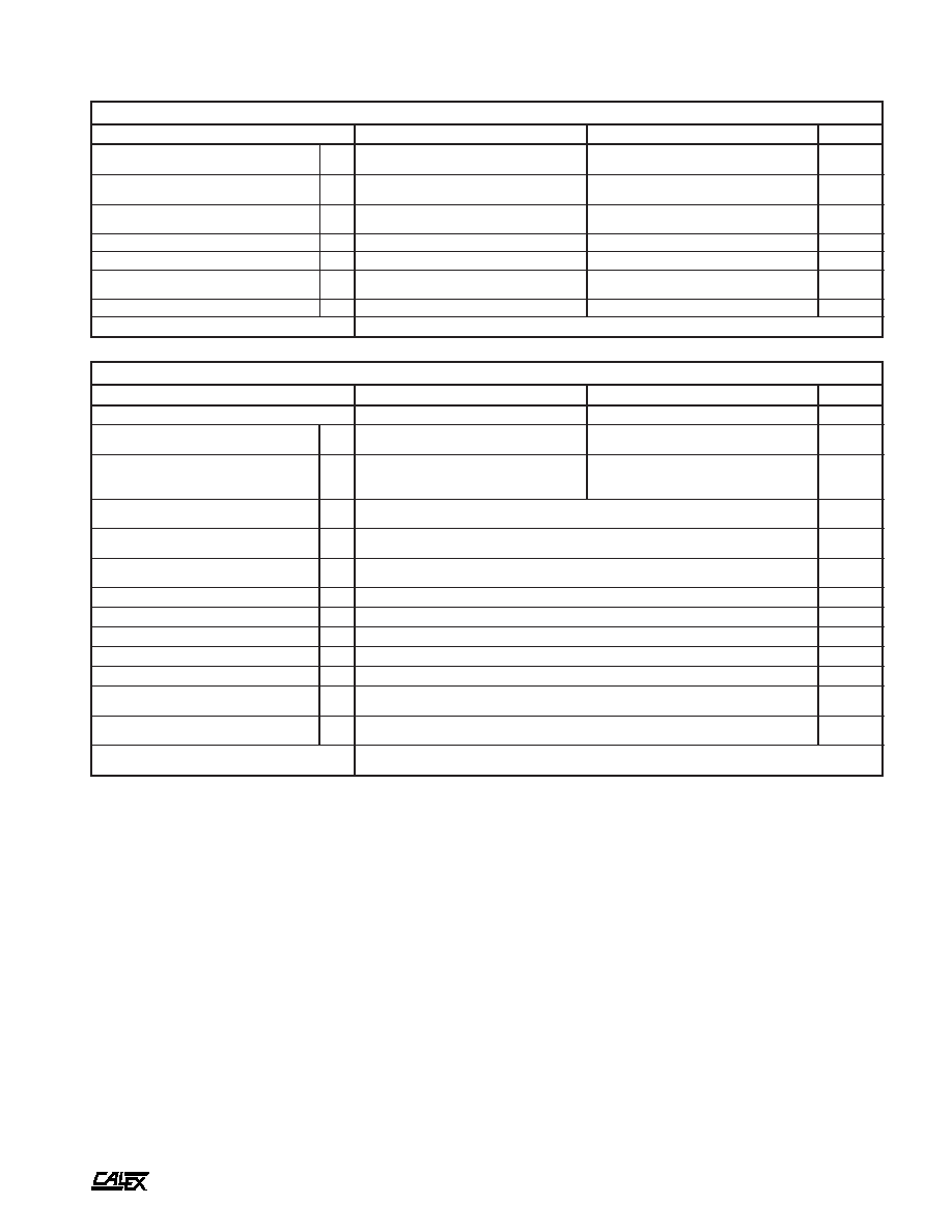
Typical Performance (Tc=25∞C; Full Rated Load).
10
11
12
13
14
LINE INPUT (VOLTS)
35
40
45
50
55
60
65
EFFICIENCY (%)
12D EFFICIENCY Vs. LINE INPUT
50% FULL LOAD
100% FULL LOAD
0
50
100
150
200
+Io PERCENT OF FULL LOAD
0
50
100
150
200
-Io PERCENT OF FULL LOAD
OUTPUT LOADING CHART
-Io
+Io
0
20
40
60
80
100
LOAD (%)
20
30
40
50
60
70
EFFICIENCY (%)
12D EFFICIENCY Vs. LOAD
LINE = 10.8VDC
LINE = 12VDC
LINE = 13.8VDC
-30
-20
-10
0
10
20
30
40
50
60
70
80
CASE TEMPERATURE (Deg C)
-0.8
-0.6
-0.4
-0.2
0.0
0.2
0.4
0.6
0.8
NORMALIZED OUTPUT (%)
OUTPUT VOLTAGE Vs CASE TEMPERATURE
POSITIVE OUTPUT
NEGATIVE OUTPUT
0
2
4
6
8
10
12
14
LINE INPUT (VOLTS)
0.00
0.05
0.10
0.15
0.20
0.25
0.30
INPUT CURRENT (AMPS)
12D INPUT CURRENT Vs. LINE INPUT
50% RATED LOAD
100% RATED LOAD
FREQUENCY (Hz)
.001
.01
.1
1
IMPEDANCE (OHMS)
OUTPUT IMPEDANCE Vs. FREQUENCY
POSITIVE OUTPUT
NEGATIVE OUTPUT
10
100
1K
10K
100K
1M