15 Watt XC Single Series DC/DC Converters
Manufacturing Company, Inc. ∑ Concord, California 94520 ∑ Ph: 925/687-4411 or 800/542-3355 ∑ Fax: 925/687-3333 ∑ www.calex.com ∑ Email: sales@calex.com
1
eco# 041007-1
DOUBLE SHIELDED
ISOLATION TRANSFORMER
LC
INPUT
FILTER
CURRENT
MODE
PWM
FEEDBACK
AMPLIFIER
SIX-SIDED SHIELDED
COPPER CASE
LOW TC
BANDGAP
REFERENCE
THERMAL SHUTDOWN
1.5 MEG || 0.01 µF
C1
C2
D1
1
2
8
+ INPUT
- INPUT
ON/OFF
6
7
4
+ OUTPUT
CMN
TRIM
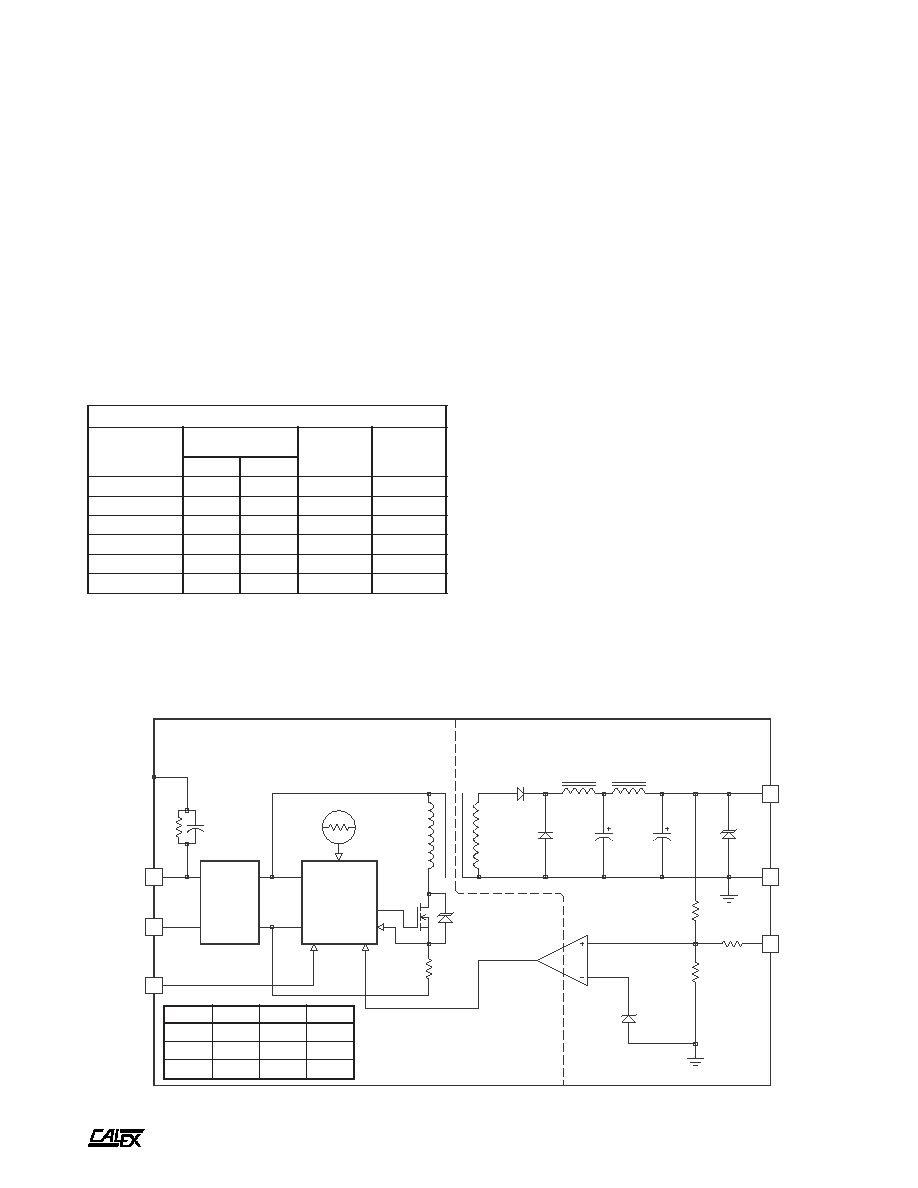
15 Watt XC Single Series Block Diagram
Description
These single output converters are designed for wide input
range, low noise, telecommunications, medical, industrial and
instrument applications. The extra wide input range (3:1) is
ideal for battery or unregulated input applications.
These converters are state-of-the-art 70kHz MOSFET
based designs that provide outstanding line and load regulation.
The single outputs are regulated with a high loop gain
current mode control method that provides linear regulator
type performance with a true, high efficiency switching DC/DC
topology. The large amount of loop gain insures excellent
input ripple rejection and line transient response.
A logic shutdown pin to control converter operation is
included. The XC Single Series is protected from output
shorts to common by a high speed, pulse by pulse digital,
current limit circuit.
t
u
p
t
u
O
1
C
2
C
1
D
5
F
µ
0
0
0
1
F
µ
8
6
V
8
.
6
2
1
F
µ
0
3
3
F
µ
5
1
V
5
1
5
1
F
µ
0
3
3
F
µ
5
1
V
8
1
Features
Extra Wide 3:1 Input Voltage Range (9-27, 24-72)
Low Noise, Highly Regulated Single Outputs
No Derating to 80∞C Case Temperature
Six-Sided Shielded Low Thermal Gradient
Copper Case
500 VDC Minimum Input to Output Isolation
Overvoltage Protected Input and Outputs
Pulse by Pulse Digital Current Limiting
Direct Output Parallel for More Power
5 Year Warranty
t
r
a
h
C
n
o
i
t
c
e
l
e
S
l
e
d
o
M
e
g
n
a
R
t
u
p
n
I
C
D
V
t
u
p
t
u
O
C
D
V
t
u
p
t
u
O
A
m
N
I
M
X
A
M
C
X
0
0
0
3
.
5
S
2
1
0
.
9
0
.
7
2
0
.
5
0
0
0
3
C
X
0
5
2
1
.
2
1
S
2
1
0
.
9
0
.
7
2
0
.
2
1
0
5
2
1
C
X
0
0
0
1
.
5
1
S
2
1
0
.
9
0
.
7
2
0
.
5
1
0
0
0
1
C
X
0
0
0
3
.
5
S
8
4
0
.
4
2
0
.
2
7
0
.
5
0
0
0
3
C
X
0
5
2
1
.
2
1
S
8
4
0
.
4
2
0
.
2
7
0
.
2
1
0
5
2
1
C
X
0
0
0
1
.
5
1
S
8
4
0
.
4
2
0
.
2
7
0
.
5
1
0
0
0
1
15 Watt XC Single Series DC/DC Converters
Manufacturing Company, Inc. ∑ Concord, California 94520 ∑ Ph: 925/687-4411 or 800/542-3355 ∑ Fax: 925/687-3333 ∑ www.calex.com ∑ Email: sales@calex.com
2
eco# 041007-1
NOTES
*
All Parameters measured at Tc=25∞C, nominal input voltage
and full rated load unless otherwise noted. Refer to the
CALEX Application Notes for the definition of terms,
measurement circuits and other information.
(2)
Determine the correct fuse size by calculating the maximum DC
current drain at low line input, maximum load then adding 20 to
25 percent. Slow blow type recommended.
(3)
No minimum load required.
(4)
Short term stability is specified after a 30 minute warm-up at full
load, and with constant line, load and ambient conditions.
(5)
The transient response is specified as the time required to settle
from 50 to 75% step load change (rise time of step = 2µSec.) to
a 1% error band.
(6)
Dynamic response is the peak overshoot voltage during the
transient response time defined in note 5 above.
(7)
The input ripple rejection is specified for DC to 120Hz ripple with
a modulation amplitude of 1% Vin.
(8)
For module protection only, also see note 2.
(9)
The logic shutdown pin is Open Collector TTL, CMOS, and relay
compatible. The input to this pin is referenced to input minus and
is protected to +100VDC.
(10) The functional temperature range is intended to give an additional
data point for use in evaluating this power supply. At the low
functional temperature the power supply will function with no
side effects, however, sustained operation at the high functional
temperature will reduce expected operational life. The data
sheet specifications are not guaranteed over the functional
temperature range.
(11) The case thermal impedance is specified as the case temperature
rise over ambient per package watt dissipated.
(12) Water Washability - Calex DC/DC converters are designed to
withstand most solder/wash processes. Careful attention should
be used when assessing the applicability in your specific
manufacturing process. Converters are not hermetically sealed.
*
s
r
e
t
e
m
a
r
a
P
t
u
p
n
I
l
e
d
o
M
C
X
0
0
0
3
.
5
S
2
1
C
X
0
5
2
1
.
2
1
S
2
1
C
X
0
0
0
1
.
5
1
S
2
1
C
X
0
0
0
3
.
5
S
8
4
C
X
0
5
2
1
.
2
1
S
8
4
C
X
0
0
0
1
.
5
1
S
8
4
s
t
i
n
U
e
g
n
a
R
e
g
a
t
l
o
V
N
I
M
X
A
M
0
.
9
0
.
7
2
0
.
4
2
0
.
2
7
C
D
V
,
e
l
p
p
i
R
d
e
t
c
e
l
f
e
R
w
b
z
H
M
0
2
-
0
P
Y
T
X
A
M
0
0
1
0
0
2
0
5
0
0
1
P
-
P
A
m
d
a
o
L
ll
u
F
t
n
e
r
r
u
C
t
u
p
n
I
d
a
o
L
o
N
P
Y
T
P
Y
T
0
0
6
1
0
2
0
4
5
1
0
3
0
2
5
1
0
3
5
9
3
5
1
0
9
3
0
2
0
8
3
0
2
A
m
y
c
n
e
i
c
i
f
f
E
P
Y
T
9
8
7
1
8
2
8
9
7
0
8
2
8
%
y
c
n
e
u
q
e
r
F
g
n
i
h
c
t
i
w
S
P
Y
T
0
7
z
H
k
t
u
p
n
I
m
u
m
i
x
a
M
,
e
g
a
t
l
o
v
r
e
v
O
e
g
a
m
a
D
o
N
s
m
0
0
1
X
A
M
2
3
5
8
C
D
V
t
u
o
k
c
o
L
e
g
a
t
l
o
v
r
e
d
n
U
5
.
8
7
1
C
D
V
,
e
m
i
T
n
o
-
n
r
u
T
r
o
r
r
E
t
u
p
t
u
O
%
1
P
Y
T
5
1
s
m
e
s
u
F
d
e
d
n
e
m
m
o
c
e
R
)
2
(
*
s
r
e
t
e
m
a
r
a
P
t
u
p
t
u
O
l
e
d
o
M
C
X
0
0
0
3
.
5
S
2
1
C
X
0
0
0
3
.
5
S
8
4
C
X
0
5
2
1
.
2
1
S
2
1
C
X
0
5
2
1
.
2
1
S
8
4
C
X
0
0
0
1
.
5
1
S
2
1
C
X
0
0
0
1
.
5
1
S
8
4
s
t
i
n
U
e
g
a
t
l
o
V
t
u
p
t
u
O
5
2
1
5
1
C
D
V
)
3
(
t
n
e
r
r
u
C
d
e
t
a
R
N
I
M
X
A
M
0
0
0
0
3
0
0
5
2
1
0
0
0
0
1
A
m
e
g
n
a
R
e
g
a
t
l
o
V
d
a
o
L
%
0
0
1
N
I
M
P
Y
T
X
A
M
5
9
.
4
0
0
.
5
5
0
.
5
0
9
.
1
1
0
0
.
2
1
0
1
.
2
1
0
9
.
4
1
0
0
.
5
1
0
1
.
5
1
C
D
V
d
a
o
L
%
0
0
1
-
0
n
o
i
t
a
l
u
g
e
R
d
a
o
L
P
Y
T
X
A
M
1
.
0
5
.
0
%
n
o
i
t
a
l
u
g
e
R
e
n
i
L
C
D
V
x
a
M
-
n
i
M
=
n
i
V
P
Y
T
X
A
M
5
0
.
0
2
.
0
%
)
4
(
y
t
il
i
b
a
t
S
m
r
e
T
t
r
o
h
S
P
Y
T
2
0
.
0
%
y
t
il
i
b
a
t
S
m
r
e
T
g
n
o
L
P
Y
T
2
.
0
s
r
H
k
/
%
)
5
(
e
s
n
o
p
s
e
R
t
n
e
i
s
n
a
r
T
P
Y
T
0
3
0
4
0
4
s
µ
)
6
(
e
s
n
o
p
s
e
R
c
i
m
a
n
y
D
P
Y
T
0
3
1
0
5
2
5
7
1
k
a
e
p
V
m
)
7
(
n
o
i
t
c
e
j
e
R
e
l
p
p
i
R
t
u
p
n
I
P
Y
T
0
6
B
d
w
b
z
H
M
0
2
-
0
,
e
s
i
o
N
P
Y
T
X
A
M
0
2
0
5
P
-
P
V
m
t
n
e
i
c
i
f
f
e
o
C
e
r
u
t
a
r
e
p
m
e
T
P
Y
T
X
A
M
0
5
0
5
1
C
∞
/
m
p
p
)
8
(
p
m
a
l
C
e
g
a
t
l
o
v
r
e
v
O
P
Y
T
8
.
6
5
1
8
1
C
D
V
o
t
n
o
i
t
c
e
t
o
r
P
t
i
u
c
r
i
C
t
r
o
h
S
s
t
u
p
t
u
O
ll
a
r
o
f
n
o
m
m
o
C
d
a
o
l
r
e
v
O
l
a
m
r
e
h
T
d
n
a
t
i
n
m
i
L
t
n
e
r
r
u
C
m
u
m
i
n
i
M
s
r
u
o
H
8
,
s
u
o
u
n
i
t
n
o
C
15 Watt XC Single Series DC/DC Converters
Manufacturing Company, Inc. ∑ Concord, California 94520 ∑ Ph: 925/687-4411 or 800/542-3355 ∑ Fax: 925/687-3333 ∑ www.calex.com ∑ Email: sales@calex.com
3
eco# 041007-1
n
i
P
n
o
i
t
c
n
u
F
1
T
U
P
N
I
+
2
T
U
P
N
I
-
4
M
I
R
T
T
U
P
T
U
O
6
T
U
P
T
U
O
+
7
N
M
C
8
F
F
O
/
N
O
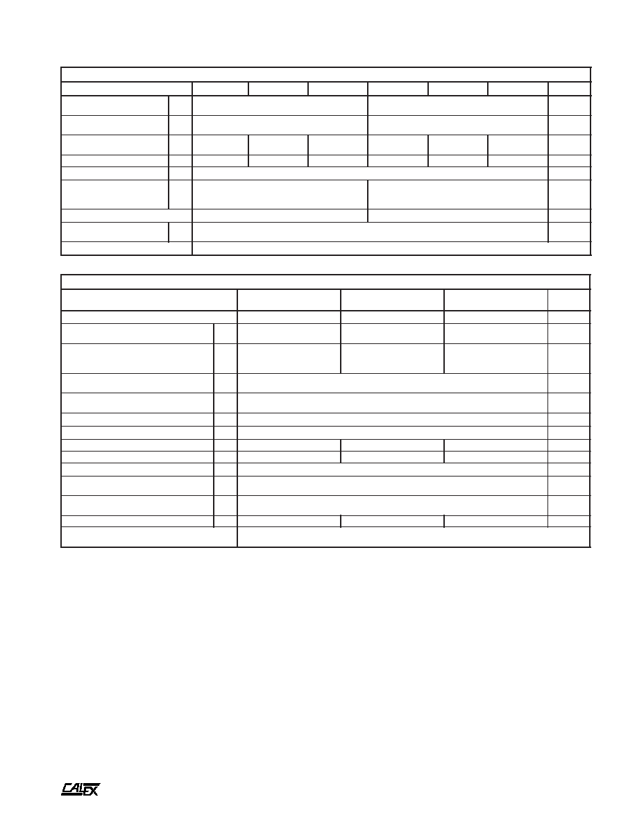
Mechanical tolerances unless otherwise noted:
X.XX dimensions: ±0.020 inches
X.XXX dimensions: ±0.005 inches
Seal around terminals is not hermetic. Do not immerse units in any
liquid.
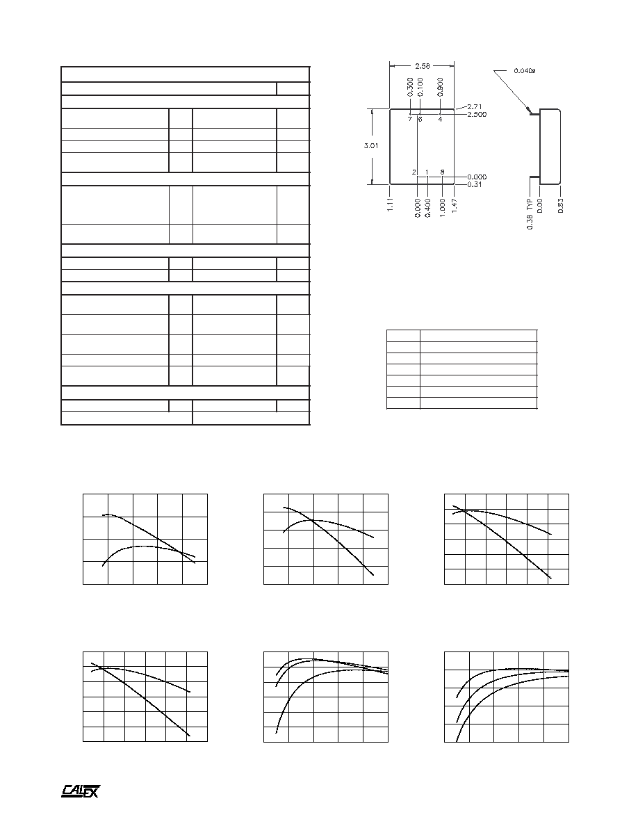
20
30
40
50
60
70
80
LINE INPUT (VOLTS)
70
72
74
76
78
80
82
EFFICIENCY (%)
48S5.3000XC EFFICIENCY Vs. LINE INPUT
50% FULL LOAD
100% FULL LOAD
0
20
40
60
80
100
LOAD (%)
55
60
65
70
75
80
85
EFFICIENCY (%)
12S5.3000XC EFFICIENCY Vs. LOAD
LINE = 9VDC
LINE = 12VDC
LINE = 36VDC
0
20
40
60
80
100
LOAD (%)
40
50
60
70
80
90
EFFICIENCY (%)
48S5.3000XC EFFICIENCY Vs. LOAD
LINE = 18VDC
LINE =
LINE = 72VDC
48VDC
5
10
15
20
25
30
LINE INPUT (VOLTS)
76
78
80
82
84
EFFICIENCY (%)
12S5.1000XC EFFICIENCY Vs. LINE INPUT
50% FULL LOAD
100% FULL LOAD
20
30
40
50
60
70
80
LINE INPUT (VOLTS)
70
72
74
76
78
80
82
EFFICIENCY (%)
48S5.3000XC EFFICIENCY Vs. LINE INPUT
50% FULL LOAD
100% FULL LOAD
5
10
15
20
25
30
LINE INPUT (VOLTS)
76
78
80
82
84
86
EFFICIENCY (%)
12S15.1000XC EFFICIENCY Vs. LINE INPUT
50% FULL LOAD
100% FULL LOAD
Typical Performance (Tc=25∞C, Vin=Nom VDC, Rated Load).
BOTTOM VIEW
SIDE VIEW
*
s
n
o
i
t
a
c
i
f
i
c
e
p
S
l
a
r
e
n
e
G
s
l
e
d
o
M
l
l
A
s
t
i
n
U
)
9
(
n
w
o
d
t
u
h
S
c
i
g
o
L
l
e
v
e
L
c
i
g
o
L
N
O
n
e
p
o
n
i
P
e
v
a
e
L
r
o
N
I
M
5
.
5
C
D
V
l
e
v
e
L
c
i
g
o
L
F
F
O
X
A
M
5
.
1
C
D
V
e
c
n
a
t
s
i
s
e
R
t
u
p
n
I
P
Y
T
0
1
s
m
h
o
k
,
t
n
e
r
r
u
C
e
l
d
I
r
e
t
r
e
v
n
o
C
w
o
L
n
i
P
n
w
o
D
t
u
h
S
P
Y
T
3
A
m
n
o
i
t
a
l
o
s
I
e
g
a
t
l
o
V
n
o
i
t
a
l
o
s
I
t
u
p
t
u
O
-
t
u
p
n
I
e
s
a
C
-
t
u
p
n
I
e
g
a
k
a
e
L
A
µ
0
1
N
I
M
N
I
M
0
0
5
0
5
2
C
D
V
t
u
p
t
u
O
o
t
t
u
p
n
I
e
c
n
a
t
i
c
a
p
a
C
P
Y
T
0
6
1
F
p
n
o
i
t
c
n
u
F
m
i
r
T
t
u
p
t
u
O
e
c
n
a
t
s
i
s
e
R
t
u
p
n
I
P
Y
T
5
1
s
m
h
o
k
e
g
n
a
R
g
n
i
m
m
a
r
g
o
r
P
N
I
M
0
1
±
%
l
a
t
n
e
m
n
o
r
i
v
n
E
e
g
n
a
R
g
n
i
t
a
r
e
p
O
e
s
a
C
g
n
i
t
a
r
e
D
o
N
N
I
M
X
A
M
5
2
-
0
8
C
∞
)
0
1
(
e
g
n
a
R
l
a
n
o
i
t
c
n
u
F
e
s
a
C
N
I
M
X
A
M
0
4
-
0
9
C
∞
e
g
n
a
R
e
g
a
r
o
t
S
N
I
M
X
A
M
5
5
-
0
0
1
C
∞
)
1
1
(
e
c
n
a
d
e
p
m
I
l
a
m
r
e
h
T
P
Y
T
4
.
4
t
t
a
W
/
C
∞
n
w
o
d
t
u
h
S
l
a
m
r
e
h
T
e
r
u
t
a
r
e
p
m
e
T
e
s
a
C
P
Y
T
0
9
C
∞
l
a
r
e
n
e
G
t
h
g
i
e
W
t
i
n
U
P
Y
T
0
.
7
z
o
t
i
K
g
n
i
t
n
u
o
M
9
S
M

15 Watt XC Single Series DC/DC Converters
Manufacturing Company, Inc. ∑ Concord, California 94520 ∑ Ph: 925/687-4411 or 800/542-3355 ∑ Fax: 925/687-3333 ∑ www.calex.com ∑ Email: sales@calex.com
4
eco# 041007-1
Typical Performance (Tc=25∞C, Vin=Nom VDC, Rated Load).
20
30
40
50
60
70
80
LINE INPUT (VOLTS)
1.0
2.0
3.0
4.0
5.0
6.0
INPUT CURRENT (mAMPS)
48S15.1000XC IDLE CURRENT
5
10
15
20
25
30
LINE INPUT (VOLTS)
0.0
0.5
1.0
1.5
2.0
2.5
INPUT CURRENT (AMPS)
12S5.3000XC INPUT CURRENT Vs. LINE INPUT VOLTAGE
50% FULL LOAD
100% FULL LOAD
10
20
30
40
50
60
70
80
LINE INPUT (VOLTS)
0.0
0.2
0.4
0.6
0.8
1.0
1.2
INPUT CURRENT (AMPS)
48S INPUT CURRENT Vs. LINE INPUT VOLTAGE
50% FULL LOAD
100% FULL LOAD
0
20
40
60
80
100
LOAD (%)
55
60
65
70
75
80
85
EFFICIENCY (%)
12S15.3000XC EFFICIENCY Vs. LOAD
LINE = 9VDC
LINE = 12VDC
LINE = 36VDC
5
10
15
20
25
30
LINE INPUT (VOLTS)
2.0
2.5
3.0
INPUT CURRENT (mAMPS)
12S15.1000XC IDLE CURRENT
0
20
40
60
80
100
LOAD (%)
40
50
60
70
80
90
EFFICIENCY (%)
48S15.3000XC EFFICIENCY Vs. LOAD
LINE = 18VDC
LINE =
LINE = 72VDC
48VDC
0
20
40
60
80
100
120
140
OUTPUT LOAD (%)
20
40
60
80
100
120
OUTPUT VOLTAGE (%)
OUTPUT VOLTAGE Vs. OUTPUT LOAD
-30
-20
-10
0
10
20
30
40
50
60
70
80
CASE TEMPERATURE (Deg C)
-0.4
-0.3
-0.2
-0.1
0.0
0.1
0.2
NORMALIZED OUTPUT (%)
OUTPUT VOLTAGE Vs. CASE TEMPERATURE
FREQUENCY (Hz)
.001
.01
.1
1
IMPEDANCE (OHMS)
OUTPUT IMPEDANCE Vs. FREQUENCY
5V OUTPUT
15V OUTPUT
10
100
1K
10K
100K
1M