 | –≠–ª–µ–∫—Ç—Ä–æ–Ω–Ω—ã–π –∫–æ–º–ø–æ–Ω–µ–Ω—Ç: 12T5.12UW | –°–∫–∞—á–∞—Ç—å:  PDF PDF  ZIP ZIP |
A
8.5 Watt UW Triple Series DC/DC Converters
2401 Stanwell Drive ∑ Concord, California 94520 ∑ Ph: 925/687-4411 or 800/542-3355 ∑ Fax: 925/687-3333 ∑ www.calex.com ∑ Email: sales@calex.com
1
3/2001, eco# 041007-1
1
2
8
6
4
3
5
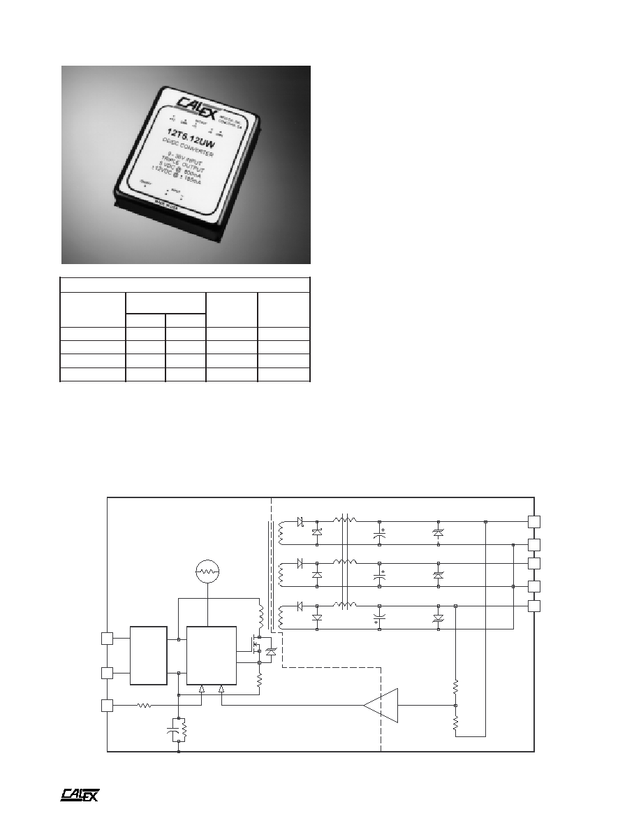
+5 OUTPUT
± CMN
+ OUTPUT
- OUTPUT
+INPUT
-INPUT
ON/OFF
THERMAL
SHUTDOWN
LC
INPUT
FILTER
PWM
CONTROL
FEEDBACK
AMPLIFIER
SHIELDED ISOLATION
TRANSFORMER
SIX-SIDED SHIELDED COPPER CASE
1.5 MEG || 0.1µF
1000 µF
100 µF
100 µF
7 +5 CMN
Features
Wide 4:1 Input Voltage Range (9-36 or 18-72VDC)
Triple Low Noise, Highly Regulated Outputs
Efficiency 70% for All Line Conditions
No Derating to 80∞C Case Temperature
Six-Sided Shielded Low Thermal
Gradient Copper Case
500 VDC Minimum Input to Output Isolation
Overvoltage Protected Outputs
Pulse by Pulse Digital Current Limiting
Five Year Warranty
8.5 Watt UW Triple Series Block Diagram
Description
The 8.5 Watt Triple Output DC/DC converters are ideal for
wide (4:1) input range applications. These units are particularly
well suited for solar powered RTUs and instruments.
They are designed with a high accuracy feedback control
circuit and coupled inductor magnetics. Each converter has
both a logic shut down pin and thermal overload protection
circuitry. All outputs and the power switch are overvoltage
protected.
These converters are encased in a six-sided, completely
shielded copper case. The UW Triple Series is covered under
the CALEX 5 Year Warranty.
t
r
a
h
C
n
o
i
t
c
e
l
e
S
l
e
d
o
M
e
g
n
a
R
t
u
p
n
I
C
D
V
s
t
u
p
t
u
O
C
D
V
s
t
u
p
t
u
O
A
m
N
I
M
X
A
M
W
U
2
1
.
5
T
2
1
0
0
.
9
0
0
.
6
3
2
1
±
,
5
5
8
1
±
,
0
0
8
W
U
5
1
.
5
T
2
1
0
0
.
9
0
0
.
6
3
5
1
±
,
5
0
5
1
±
,
0
0
8
W
U
2
1
.
5
T
8
4
0
0
.
8
1
0
0
.
2
7
2
1
±
,
5
5
8
1
±
,
0
0
8
W
U
5
1
.
5
T
8
4
0
0
.
8
1
0
0
.
2
7
5
1
±
,
5
0
5
1
±
,
0
0
8
A
8.5 Watt UW Triple Series DC/DC Converters
2401 Stanwell Drive ∑ Concord, California 94520 ∑ Ph: 925/687-4411 or 800/542-3355 ∑ Fax: 925/687-3333 ∑ www.calex.com ∑ Email: sales@calex.com
2
3/2001, eco# 041007-1
(7)
The input ripple rejection is specified for DC to 120Hz ripple with
a modulation amplitude of 1% Vin.
(8)
For module protection only, see also note 2.
(9)
The logic shutdown pin is Open Collector TTL, CMOS, and relay
compatible. The input to this pin is referenced to input minus.
(10) The functional temperature range is intended to give an additional
data point for use in evaluating this power supply. At the low
functional temperature the power supply will function with no
side effects, however, sustained operation at the high functional
temperature will reduce expected operational life. The data
sheet specifications are not guaranteed over the functional
temperature range.
(11) The case thermal impedance is specified as the case temperature
rise over ambient per package watt dissipated.
(12) Specifications subject to change without notice.
(13) Water Washability - Calex DC/DC converters are designed to
withstand most solder/wash processes. Careful attention should
be used when assessing the applicability in your specific
manufacturing process. Converters are not hermetically sealed.
NOTES:
*
All parameters measured at Tc=25∞C, nominal input voltage
and full rated load unless otherwise noted. Refer to the
CALEX Application Notes for the definition of terms,
measurement circuits and other information.
(2)
Determine the correct fuse size by calculating the maximum DC
current drain at low line input, maximum load and then adding
20 to 25 percent.
(3)
The module will not be damaged if run at less than minimum
load. Regulation can degrade with less than minimum load or
substantial load imbalance.
(4)
Short term stability is specified after a 30 minute warm-up at full
load, and with constant line, load and ambient conditions.
(5)
The transient response is specified as the time required to settle
from 25 to 75% step load change (rise time of step = 2µ Sec.) to
a 1% error band.
(6)
Dynamic response is the peak overshoot voltage during the
transient response time defined in note 5 above.
*
s
r
e
t
e
m
a
r
a
P
t
u
p
n
I
l
e
d
o
M
W
U
2
1
.
5
T
2
1
W
U
5
1
.
5
T
2
1
W
U
2
1
.
5
T
8
4
W
U
5
1
.
5
T
8
4
s
t
i
n
U
e
g
n
a
R
e
g
a
t
l
o
V
N
I
M
X
A
M
0
0
.
9
0
0
.
6
3
0
0
.
8
1
0
0
.
2
7
C
D
V
w
b
z
H
M
0
2
-
0
,
e
l
p
p
i
R
d
e
t
c
e
l
f
e
R
P
Y
T
X
A
M
0
3
0
6
P
-
P
A
m
d
a
o
L
ll
u
F
t
n
e
r
r
u
C
t
u
p
n
I
d
a
o
L
o
N
P
Y
T
P
Y
T
8
0
9
9
1
8
0
9
9
1
0
3
2
5
1
0
3
2
5
1
A
m
y
c
n
e
i
c
i
f
f
E
P
Y
T
8
7
%
y
c
n
e
u
q
e
r
F
g
n
i
h
c
t
i
w
S
P
Y
T
5
5
z
H
k
s
m
0
0
1
,
e
g
a
t
l
o
v
r
e
v
O
t
u
p
n
I
m
u
m
i
x
a
M
e
g
a
m
a
d
o
N
X
A
M
5
4
5
8
C
D
V
r
o
r
r
E
t
u
p
t
u
O
%
1
,
e
m
i
T
n
o
-
n
r
u
T
P
Y
T
0
2
1
s
m
e
s
u
F
d
e
d
n
e
m
m
o
c
e
R
)
2
(
*
s
r
e
t
e
m
a
r
a
P
t
u
p
t
u
O
l
e
d
o
M
W
U
2
1
.
5
T
2
1
W
U
5
1
.
5
T
2
1
W
U
2
1
.
5
T
8
4
W
U
5
1
.
5
T
8
4
W
U
2
1
.
5
T
2
1
W
U
2
1
.
5
T
8
4
W
U
5
1
.
5
T
2
1
W
U
5
1
.
5
T
8
4
s
t
i
n
U
e
g
a
t
l
o
V
t
u
p
t
u
O
5
2
1
±
5
1
±
C
D
V
)
3
(
t
n
e
r
r
u
C
d
e
t
a
R
N
I
M
X
A
M
0
0
2
0
0
8
0
5
5
8
1
0
5
0
5
1
A
m
e
g
n
a
R
e
g
a
t
l
o
V
d
a
o
L
%
0
0
1
N
I
M
P
Y
T
X
A
M
0
9
.
4
0
0
.
5
0
1
.
5
6
7
.
1
1
0
0
.
2
1
4
2
.
2
1
5
5
.
4
1
0
0
.
5
1
5
4
.
5
1
C
D
V
d
a
o
L
x
a
M
-
n
i
M
n
o
i
t
a
l
u
g
e
R
d
a
o
L
P
Y
T
X
A
M
0
.
2
5
.
3
0
.
2
0
.
3
0
.
2
0
.
3
%
n
o
i
t
a
l
u
g
e
R
e
n
i
L
C
D
V
x
a
M
-
n
i
M
=
n
i
V
P
Y
T
X
A
M
5
.
0
5
.
1
5
.
0
0
.
1
5
.
0
0
.
1
%
)
4
(
y
t
il
i
b
a
t
S
m
r
e
T
t
r
o
h
S
P
Y
T
2
0
.
0
%
y
t
il
i
b
a
t
S
m
r
e
T
g
n
o
L
P
Y
T
2
.
0
s
r
H
k
/
%
)
5
(
e
s
n
o
p
s
e
R
t
n
e
i
s
n
a
r
T
P
Y
T
0
4
s
µ
)
6
(
e
s
n
o
p
s
e
R
c
i
m
a
n
y
D
P
Y
T
5
7
0
7
0
5
k
a
e
p
V
m
)
7
(
n
o
i
t
c
e
j
e
R
e
l
p
p
i
R
t
u
p
n
I
P
Y
T
5
3
B
d
w
b
z
H
M
0
2
-
0
,
e
s
i
o
N
P
Y
T
X
A
M
0
2
0
5
P
-
P
V
m
t
n
e
i
c
i
f
f
e
o
C
e
r
u
t
a
r
e
p
m
e
T
P
Y
T
X
A
M
0
2
1
0
0
2
C
∞
/
m
p
p
)
8
(
p
m
a
l
C
e
g
a
t
l
o
v
r
e
v
O
P
Y
T
8
.
6
0
.
5
1
0
.
8
1
C
D
V
o
t
n
o
i
t
c
e
t
o
r
P
t
i
u
c
r
i
C
t
r
o
h
S
s
t
u
p
t
u
O
ll
a
r
o
f
n
o
m
m
o
C
d
a
o
l
r
e
v
O
l
a
m
r
e
h
T
d
n
a
t
i
m
i
L
t
n
e
r
r
u
C
m
u
m
i
n
i
M
s
r
u
o
H
8
,
s
u
o
u
n
i
t
n
o
C
A
8.5 Watt UW Triple Series DC/DC Converters
2401 Stanwell Drive ∑ Concord, California 94520 ∑ Ph: 925/687-4411 or 800/542-3355 ∑ Fax: 925/687-3333 ∑ www.calex.com ∑ Email: sales@calex.com
3
3/2001, eco# 041007-1
n
i
P
n
o
i
t
c
n
u
F
1
T
U
P
N
I
+
2
T
U
P
N
I
-
3
T
U
P
T
U
O
5
1
+
/
2
1
+
4
]
1
[
N
M
C
T
U
P
T
U
O
±
5
T
U
P
T
U
O
5
1
-
/
2
1
-
6
T
U
P
T
U
O
5
+
7
]
1
[
N
M
C
5
+
8
F
F
O
/
N
O
.
y
ll
a
n
r
e
t
n
i
d
e
t
c
e
n
n
o
c
e
r
a
7
&
4
s
n
i
P
:
e
t
o
N
]
1
[
CURVES APPLICABLE TO BOTH ±12 AND ±15 VDC
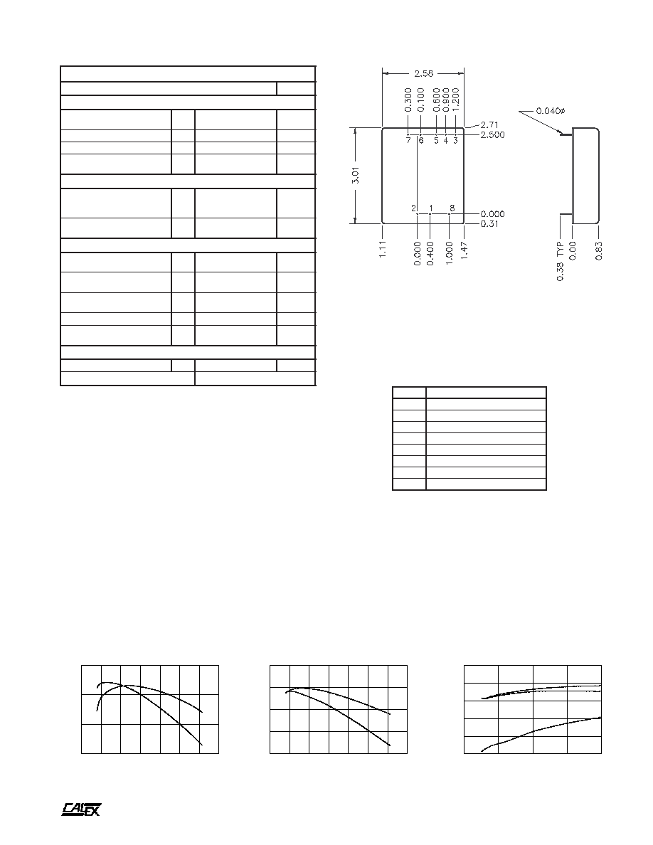
Typical Performance (Tc=25∞C, Full Rated Load).
Mechanical tolerances unless otherwise noted:
X.XX dimensions: ±0.020 inches
X.XXX dimensions: ±0.005 inches
Seal around terminals is not hermetic. Do not immerse units in any
liquid.
BOTTOM VIEW
SIDE VIEW
*
s
n
o
i
t
a
c
i
f
i
c
e
p
S
l
a
r
e
n
e
G
s
l
e
d
o
M
l
l
A
s
t
i
n
U
)
9
(
n
w
o
d
t
u
h
S
c
i
g
o
L
l
e
v
e
L
c
i
g
o
L
N
O
n
e
p
O
n
i
P
e
v
a
e
L
r
o
N
I
M
4
.
2
C
D
V
l
e
v
e
L
c
i
g
o
L
F
F
O
X
A
M
2
.
1
C
D
V
e
c
n
a
t
s
i
s
e
R
t
u
p
n
I
P
Y
T
0
1
s
m
h
o
k
,
t
n
e
r
r
u
C
e
l
d
I
r
e
t
r
e
v
n
o
C
w
o
L
n
i
P
n
w
o
D
t
u
h
S
P
Y
T
0
.
6
A
m
n
o
i
t
a
l
o
s
I
e
g
a
t
l
o
V
n
o
i
t
a
l
o
s
I
e
g
a
k
a
e
L
A
µ
0
1
t
u
p
t
u
O
-
t
u
p
n
I
N
I
M
0
0
5
C
D
V
t
u
p
t
u
O
o
t
t
u
p
n
I
e
c
n
a
t
i
c
a
p
a
C
P
Y
T
0
9
1
F
p
l
a
t
n
e
m
n
o
r
i
v
n
E
e
g
n
a
R
g
n
i
t
a
r
e
p
O
e
s
a
C
g
n
i
t
a
r
e
D
o
N
N
I
M
X
A
M
5
2
-
0
8
C
∞
)
0
1
(
e
g
n
a
R
l
a
n
o
i
t
c
n
u
F
e
s
a
C
N
I
M
X
A
M
0
4
-
0
9
C
∞
e
g
n
a
R
e
g
a
r
o
t
S
N
I
M
X
A
M
5
5
-
0
0
1
C
∞
)
1
1
(
e
c
n
a
d
e
p
m
I
l
a
m
r
e
h
T
P
Y
T
4
.
4
t
t
a
W
/
C
∞
n
w
o
d
t
u
h
S
l
a
m
r
e
h
T
e
r
u
t
a
r
e
p
m
e
T
e
s
a
C
P
Y
T
0
9
C
∞
l
a
r
e
n
e
G
t
h
g
i
e
W
t
i
n
U
P
Y
T
0
.
7
z
o
t
i
K
g
n
i
t
n
u
o
M
9
S
M
5
10
15
20
25
30
35
40
LINE INPUT (VOLTS)
65
70
75
80
EFFICIENCY (%)
12T5.15UW EFFICIENCY Vs. LINE INPUT
50% FULL LOAD
100% FULL LOAD
10
20
30
40
50
60
70
80
LINE INPUT (VOLTS)
65
70
75
80
85
EFFICIENCY (%)
48T5.15UW EFFICIENCY Vs. LINE INPUT
50% FULL LOAD
100% FULL LOAD
20
40
60
80
100
LOAD (%)
60
65
70
75
80
85
EFFICIENCY (%)
12T5.15UW EFFICIENCY Vs. LOAD
LINE = 9VDC
LINE = 12VDC
LINE = 36VDC
A
8.5 Watt UW Triple Series DC/DC Converters
2401 Stanwell Drive ∑ Concord, California 94520 ∑ Ph: 925/687-4411 or 800/542-3355 ∑ Fax: 925/687-3333 ∑ www.calex.com ∑ Email: sales@calex.com
4
3/2001, eco# 041007-1
30
40
50
60
70
80
90
100
-15 VOLT LOAD (%)
-1.0
-0.8
-0.6
-0.4
-0.2
-0.0
0.2
0.4
NORMALIZED OUTPUT VOLTAGE (%)
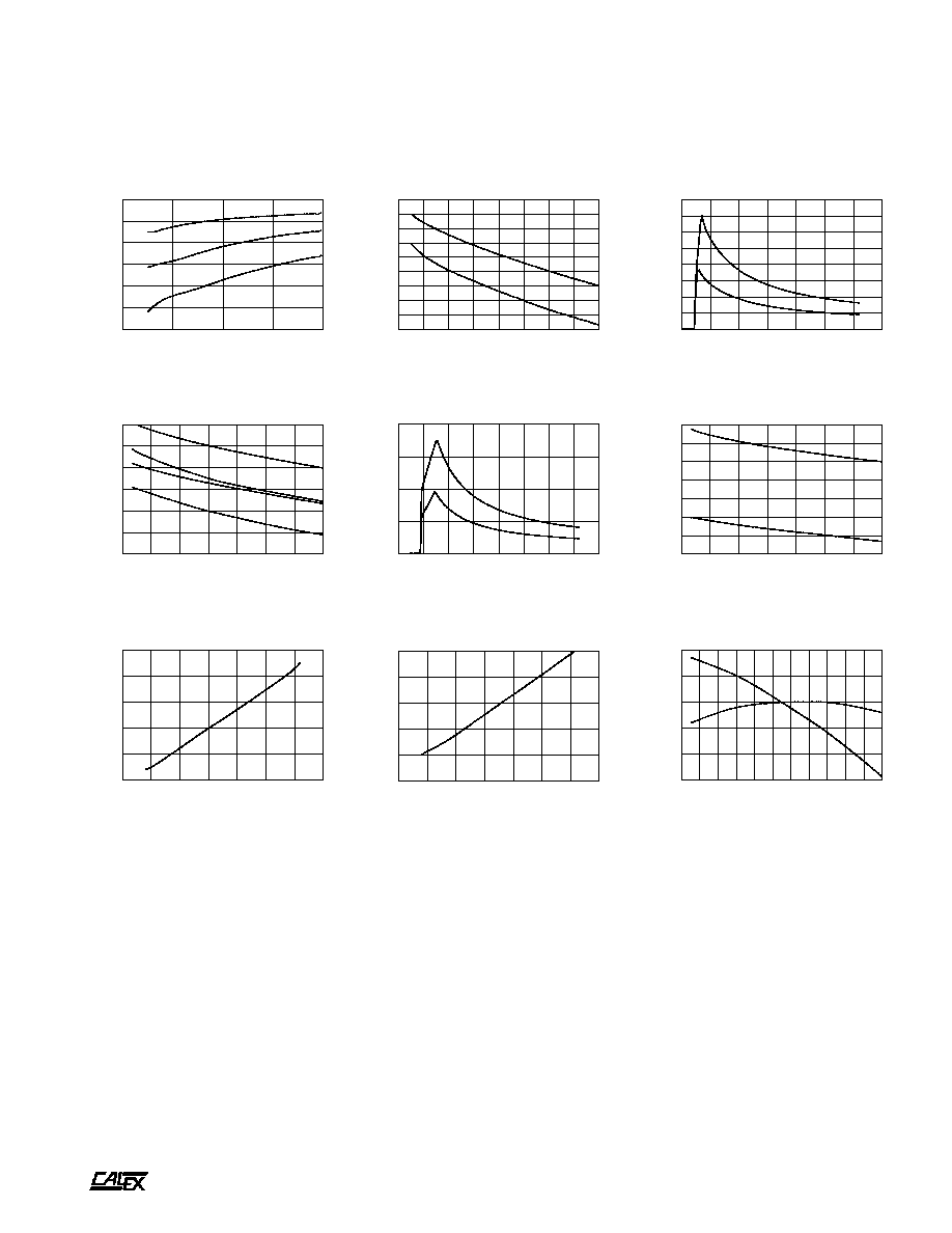
-15 VOLT OUTPUT*
CROSS REGULATION Vs. PERCENT OF FULL LOAD
+5 FULL LOAD
+5 MIN LOAD
+15 FULL LOAD
+15 FULL LOAD
0
10
20
30
40
50
60
70
80
LINE INPUT (VOLTS)
0.0
0.2
0.4
0.6
0.8
INPUT CURRENT (AMPS)
48T INPUT CURRENT Vs. LINE INPUT VOLTAGE
50% FULL LOAD
100% FULL LOAD
30
40
50
60
70
80
90
100
+15 VOLT LOAD (%)
-2.0
-1.5
-1.0
-0.5
0.0
0.5
1.0
NORMALIZED OUTPUT VOLTAGE (%)
+15 VOLT OUTPUT*
CROSS REGULATION Vs. PERCENT OF FULL LOAD
+5 FULL LOAD
-15 FULL LOAD
+5 FULL LOAD
-15 MIN LOAD
+5 MIN LOAD
-15 FULL LOAD
+5 MIN LOAD
-15 MIN LOAD
5
10
15
20
25
30
35
40
LINE INPUT (VOLTS)
0.0
0.2
0.4
0.6
0.8
1.0
1.2
1.4
1.6
INPUT CURRENT (AMPS)
12T INPUT CURRENT Vs. LINE INPUT VOLTAGE
50% FULL LOAD
100% FULL LOAD
20
40
60
80
100
LOAD (%)
55
60
65
70
75
80
85
EFFICIENCY (%)
48T5.15UW EFFICIENCY Vs. LOAD
LINE = 18VDC
LINE = 48VDC
LINE = 72VDC
Typical Performance (Tc=25∞C, Full Rated Load).
CURVES APPLICABLE TO BOTH ±12 AND ±15 VDC
20
30
40
50
60
70
80
90
100
5 VOLT LOAD (%)
-1.5
-1.0
-0.5
0.0
0.5
1.0
1.5
2.0
2.5
3.0
NORMALIZED OUTPUT VOLTAGE (%)
+5 VOLT OUTPUT*
CROSS REGULATION Vs. PERCENT OF FULL LOAD
+\-15 FULL LOAD
+\-15 MIN LOAD
-30
-20
-10
0
10
20
30
40
50
60
70
80
CASE TEMPERATURE (Deg C)
-0.6
-0.4
-0.2
0.0
0.2
0.4
NORMALIZED OUTPUT (%)
OUTPUT VOLTAGE Vs. CASE TEMPERATURE
+/-15 OUTPUT
+5 OUTPUT
10
20
30
40
50
60
70
80
LINE INPUT (VOLTS)
6
7
8
9
10
11
INPUT CURRENT (mAMPS)
48T IDLE CURRENT Vs. LINE INPUT
5
10
15
20
25
30
35
40
LINE INPUT (VOLTS)
6
8
10
12
14
16
INPUT CURRENT (mAMPS)
12T IDLE CURRENT Vs. LINE INPUT