 | –≠–ª–µ–∫—Ç—Ä–æ–Ω–Ω—ã–π –∫–æ–º–ø–æ–Ω–µ–Ω—Ç: 162MK | –°–∫–∞—á–∞—Ç—å:  PDF PDF  ZIP ZIP |

A
2401 Stanwell Drive ∑ Concord, California 94520 ∑ Ph: 925/687-4411 or 800/542-3355 ∑ Fax: 925/687-3333 ∑ www.calex.com ∑ Email: sales@calex.com
1
4/2001
Model 163MK Bridgesensor
FIGURE 1. Complete block diagram of the 163MK Bridgesensor
163MK Block Diagram
Features
!
Pin for Pin Replacement for Model 161MK
!
Compact, complete and convenient to use
!
Easy access to all trim adjustments
!
Simplifies Single and Half Bridge Applications
!
On card Bridge Balance Trimpot eliminates
additional wiring for Three Wire applications
!
Changing Bridge supply voltage is easy using
on board trimpot with adjustment range from
+4 to +10 VDC
!
Bridge supply lead resistance effects can be
ignored with built-in remote sensing
!
Filter frequency can be changed with the flick
of a DIP switch
Description
The CALEX 163MK Bridgesensor is a complete signal
conditioning system on a card designed expressly for single
half, or full bridge transducers. The 163MK consists of a high
performance instrumentation amplifier, a user adjustable
active filter, high stability bridge supply and all of the required
circuitry, trimpots, etc., so that only point to point wiring need
be made to the inputs, outputs and power to have a complete
signal conditioning system up and running.
The mounting kit provides coarse and fine gain adjustment
trimpots along with input and output offset adjustments, DIP
switches for setting the bridge supply output and active low
pass filter cutoff frequency. Provisions are also provided to
mount a quarter bridge completion resistor and a calibration
resistor which can be wired to an external CAL switch. Two
close tracking 1/2 bridge completion resistors are also included.
Application of the 163MK is easy by following the detailed
applications information that is included with this data sheet
and full engineering specifications allow easy and complete
worst case analysis.
163MK vs 161MK
The Model 163MK is a pin compatible replacement for the
Model 161MK which is no longer available. The one major
difference is that the 163MK does not have a reference
voltage on pin J. Pin J is connected to COM, pins B and 2. The
163MK also has a high frequency input filter to reduce EMI.
This filter has a high frequency cutoff above 200KHz which is
well above the requirements of weighing systems. See
figure 3 163MK INPUT AMP RESPONSE. The output of the
instrumentation amplifier, pin P, is not inverted with respect to
the Filter Output as it was in the 161MK. The OUTPUT
OFFSET pot, RP1, is disabled by a jumper, J5, which must be
removed to use RP1. The external OUTPUT OFFSET input,
pin K, is always active.
Applications using the 161MK can use the 163MK simply by
inserting the board and making the typical zero and span
adjustments. No wiring changes should be required.
A
B
C
D
E
F
H
J
K
L
M
N
P
R
S
1
2
3
4
5
6
7
8
9
10
11
12
13
14
15
J2
+15V
+SENSE
COM
KEY
15V
+EXCITATION
SENSE
NC
OUTPUT
OFFSET
INPUT
+INPUT
FILTER OUT
AMP OUT
1/2 BRIDGE
COMPLETION
BRIDGE
BALANCE
CALIBRATION
SWITCH
COM
NC
NC
NC
J1
TP1
ST3
ST4
1/4 BRIDGE
COMPLETION
RESISTOR
ST1
ST2
CALIBRATION
RESISTOR
J3
J4
+EXCITATION
+SENSE
SENSE
EXCITATION
BRIDGE
EXCITATION
SUPPLY
SW-1
RP2 BRIDGE SUPPLY
ADJUST
REMOVE J5 TO ADJUST OUTPUT
OFFSET, RP1
TP4
TP3
FILTER OUT
J5
RP1
OUTPUT
OFFSET
RX1
RX2
27K
RP3 INPUT OFFSET
X2 GAIN FILTER AMPLIFIER
100
RG
+
RP4
R6
196
FINE
GAIN
RP5
COARSE 1K
20
10K
10K
+SENSE
R18
56.2K
SENSE
RP6
BRIDGE
BALANCE
TP2
AMP OUT
SW2
SW4
CX2
.22µF
.022µF
.22µF
.022µF
CX1
SW3
SW5

A
2401 Stanwell Drive ∑ Concord, California 94520 ∑ Ph: 925/687-4411 or 800/542-3355 ∑ Fax: 925/687-3333 ∑ www.calex.com ∑ Email: sales@calex.com
2
4/2001
Model 163MK Bridgesensor
Specifications
Conditions (Unless Noted): Ta = 25∞C, Vs = ±15 VDC, G = 500 V/V
r
e
t
e
m
a
r
a
P
m
u
m
i
n
i
M
l
a
c
i
p
y
T
m
u
m
i
x
a
M
s
t
i
n
U
)
1
(
r
e
i
f
i
l
p
m
A
e
g
n
a
R
n
i
a
G
)
2
(
e
l
b
a
t
s
u
j
d
A
r
o
t
s
i
s
e
R
t
e
S
l
a
n
r
e
t
x
E
/
w
0
0
1
2
0
0
5
0
0
0
5
V
/
V
n
o
i
t
a
u
q
E
n
i
a
G
)
2
-
G
(
/
0
0
0
,
0
0
1
=
g
R
s
m
h
o
V
/
V
0
0
0
1
<
G
<
2
y
c
a
r
u
c
c
A
n
o
i
t
a
u
q
E
n
i
a
G
3
%
e
r
u
t
a
r
e
p
m
e
T
n
i
a
G
t
n
e
i
c
i
f
f
e
o
C
s
t
o
p
m
i
r
T
/
w
e
n
o
l
a
r
e
i
f
il
p
m
A
5
7
5
2
0
5
1
0
0
1
C
∞
/
m
p
p
g
n
i
w
S
t
u
p
t
u
O
V
0
1
±
,
y
t
i
r
a
e
n
il
n
o
N
2
0
0
.
0
5
0
0
.
0
%
t
u
p
t
u
O
d
n
a
t
u
p
n
I
,
e
g
a
t
l
o
V
t
e
s
f
f
O
o
r
e
Z
o
t
e
l
b
a
t
s
u
j
d
A
)
3
(
t
f
i
r
D
p
u
m
r
a
W
1
±
5
±
V
µ
t
e
s
f
f
O
t
u
p
n
I
:
e
r
u
t
a
r
e
p
m
e
T
.
s
V
V
/
V
2
=
G
V
/
V
0
0
0
1
=
G
.
x
a
M
,
s
n
i
a
G
r
e
h
t
O
t
A
2
±
2
.
0
±
)
G
/
0
2
(
±
2
.
0
±
0
1
±
1
±
C
∞
/
V
µ
y
l
p
p
u
S
r
e
w
o
P
.
s
V
1
±
5
±
V
/
V
µ
e
g
n
a
R
t
s
u
j
d
A
t
e
s
f
f
O
t
u
p
t
u
O
± 0
1
V
)
4
(
t
n
e
r
r
u
C
s
a
i
B
t
u
p
n
I
e
r
u
t
a
r
e
p
m
e
T
.
s
V
1
0
4
5
A
n
C
∞
/
A
p
t
n
e
r
r
u
C
t
e
s
f
f
O
t
u
p
n
I
e
r
u
t
a
r
e
p
m
e
T
.
s
V
1
0
4
5
A
n
C
∞
/
A
p
)
5
(
e
c
n
a
d
e
p
m
I
t
u
p
n
I
F
µ
7
4
0
0
.
|
|
s
m
h
o
G
4
e
d
o
M
n
o
m
m
o
C
:
e
g
a
t
l
o
V
t
u
p
n
I
e
s
n
o
p
s
e
R
r
a
e
n
i
L
,
e
g
n
a
R
m
u
m
i
x
a
M
9
±
5
1
±
C
D
V
:
)
6
(
R
M
C
)
7
(
z
H
0
6
-
C
D
,
w
b
z
H
k
1
)
7
(
z
H
0
6
-
C
D
,
w
b
z
H
0
1
0
0
1
0
2
1
B
d
:
e
g
a
t
l
o
V
e
s
i
o
N
t
u
p
n
I
z
H
0
1
-
z
H
1
.
0
z
H
0
0
1
-
z
H
0
1
3
.
0
1
P
-
P
V
µ
:
t
n
e
r
r
u
C
z
H
0
1
-
z
H
1
.
0
0
8
P
-
P
A
p
:
t
u
p
t
u
O
d
e
t
a
R
d
a
o
L
m
h
o
k
2
,
e
g
a
t
l
o
V
t
n
e
r
r
u
C
e
c
n
a
t
i
c
a
p
a
C
d
a
o
L
± 0
1
±5
0
0
0
1
C
D
V
A
m
F
p
t
i
u
c
r
i
C
t
r
o
h
S
e
t
u
n
i
m
1
:
)
8
(
e
s
n
o
p
s
e
R
c
i
m
a
n
y
D
h
t
d
i
w
d
n
a
B
l
a
n
g
i
S
ll
a
m
S
)
3
e
r
u
g
i
f
e
e
s
(
e
s
n
o
p
s
e
R
p
m
A
e
l
b
a
t
s
u
j
d
A
z
H
k
:
)
9
(
r
e
t
l
i
F
s
s
a
P
w
o
L
s
e
l
o
P
f
o
r
e
b
m
u
N
)
N
o
t
P
n
i
P
(
n
i
a
G
C
D
f
f
O
ll
o
R
2
2
+
0
4
V
/
V
c
e
D
/
B
d
)
0
1
(
y
l
p
p
u
S
n
o
i
t
a
t
i
c
x
E
e
g
d
i
r
B
:
e
g
n
a
R
t
n
e
m
t
s
u
j
d
A
t
u
p
t
u
O
t
o
p
m
i
r
T
/
w
4
0
1
C
D
V
t
n
e
r
r
u
C
t
u
p
t
u
O
0
0
2
1
A
m
I
n
o
i
t
a
l
u
g
e
R
d
a
o
L
L
A
m
0
2
1
-
0
=
2
0
.
0
5
0
.
0
%
C
D
V
6
1
-
5
.
4
1
=
n
i
V
n
o
i
t
a
l
u
g
e
R
e
n
i
L
5
0
0
.
0
1
0
.
0
V
/
%
:
)
1
1
(
y
t
il
i
b
a
t
S
m
r
e
T
t
r
o
h
S
m
r
e
T
g
n
o
L
e
r
u
t
a
r
e
p
m
e
T
.
s
V
5
0
.
0
2
.
0
0
4
0
8
s
r
H
4
2
/
%
s
r
H
k
/
%
C
∞
/
m
p
p
t
f
i
r
D
p
u
-
m
r
a
W
1
0
.
0
%
n
o
i
t
c
e
t
o
r
P
t
i
u
c
r
i
C
t
r
o
h
S
s
e
t
u
n
i
m
0
1
-
m
r
e
T
t
r
o
h
S
z
H
k
1
-
z
H
0
1
,
e
s
i
o
N
t
u
p
t
u
O
0
0
2
P
-
P
V
µ
n
o
i
t
e
l
p
m
o
C
e
g
d
i
r
B
f
l
a
H
e
u
l
a
V
e
c
n
a
t
s
i
s
e
R
l
a
n
i
m
o
N
0
1
s
m
h
o
k
y
c
a
r
u
c
c
A
l
a
i
t
i
n
I
%
1
.
0
%
g
n
i
k
c
a
r
T
e
r
u
t
a
r
e
p
m
e
T
5
C
∞
/
m
p
p
e
g
d
i
r
B
m
h
o
0
5
3
,
e
g
n
a
R
t
n
e
m
t
s
u
j
d
A
e
c
n
a
l
a
B
5
1
±
V
m
s
t
n
e
m
e
r
i
u
q
e
R
r
e
w
o
P
:
e
g
a
t
l
o
V
e
c
n
a
m
r
o
f
r
e
P
d
e
t
a
R
g
n
i
t
a
r
e
p
O
± 3
1
± 5
1
± 6
1
C
D
V
)
2
1
(
t
n
e
r
r
u
C
± 2
1
A
m
l
a
t
n
e
m
n
o
r
i
v
n
E
:
t
n
e
i
b
m
A
g
n
i
t
a
r
e
p
O
e
g
a
r
o
t
S
5
2
-
0
4
-
5
5
0
8
C
∞

A
2401 Stanwell Drive ∑ Concord, California 94520 ∑ Ph: 925/687-4411 or 800/542-3355 ∑ Fax: 925/687-3333 ∑ www.calex.com ∑ Email: sales@calex.com
3
4/2001
Model 163MK Bridgesensor
Notes:
(1) Specifications referred to the filter output (Pin N).
(2) Using on board coarse and fine gain adjust trimpots.
(3) Warm-up drift is specified as the input offset drift for the first
5 minutes after the application of power with G = 1000 V/V,
Bridge supply = 10V driving a 350 ohm bridge.
(4) Measured at 25∞C Ambient with unit fully warmed up.
(5) Measured from -Input to +Input or input with respect to
ground.
(6) Specified with 350 ohm bridge as source impedance.
(7) Filter frequency set with DIP switches.
(8) Small signal response, switch or resistor/capacitor selectable,
see applications section.
(9) The low pass filter cutoff frequency is adjustable to 10, 100
and 1000 Hz using the onboard DIP switches and from 1 Hz
to 10 KHz using external resistors and capacitors.
(10) Bridge supply must be operated with +Sense connected to
the Bridge Supply Pin and with -Sense connected to Common.
(11) Stability is defined after a 5 minute warm-up period and with
constant line, load and ambient temperature unless otherwise
specified.
(12) Quiescent current for amplifiers only, the current drawn from
the bridge supply must be added to the +15 VDC current
drain for total current draw.
Functional Description
The CALEX Model 163MK is a completely self contained
single channel signal conditioning system on a card. This
device offers the high performance and reliability of surface
mount circuitry with the completeness of a mounting kit
containing all trimpots and components needed for operation.
All that needs to be added is power and transducer inputs to
get a conditioned output suitable for driving A/D converters,
panel meters, indicators, or PC based controllers.
Instrumentation Amplifier
The heart of the 163MK is the high performance instrumentation
amplifier. This amplifier features low noise, low drift and high
accuracy along with trimpot adjustments for coarse/fine gain
and input offset voltage. The direct instrumentation amplifier
output is brought out to Pin P on the 163MK, through a 100
ohm isolation resistor. This output is also brought out to the
test point AMP OUT at the trimpot edge of the mounting kit.
The trimpots allow a gain adjustment range of 100 to 500 V/
V with a coarse and fine gain adjuster (clockwise rotation
increases gain). A user supplied resistor can be used in place
of the trimpots (see equations below) to get any gain from 2
to 5000V/V (referred to filtered output). To use an external
resistor remove R6 from the mounting kit to disable the
trimpots, then calculate the required value for RG and solder
it on the mounting kit in the spot provided.
The gain equation accuracy is ±3 percent for gains from 2 to
1000 V/V.
Equation 1: User supplied resistor value required to set gain
with respect to Pin N, filtered output.
Equation 2: User supplied resistor value required to set gain
with respect to Pin P, amplifier direct output. NOTE: If a fixed
resistor is used for RG, then resistor R6 should be removed
from the 163MK to disable the gain trimpots. If a slightly higher
RG is used, the pots and R6 can be used to provide a small
adjustment range.
Example Resistor Values for Common Gains (to Filtered
Output):
The instrumentation amplifier also has a trimpot adjustment
for input offset voltage, this trimpot should be used to null the
instrumentation amplifier offset only. System offsets should
be adjusted out using the Bridge Balance or the Output Offset
feature (see applications section for more information) to
retain minimum offset drift of the instrumentation amplifier.
The 163MK inputs should be placed as close to the transducer
as possible. This will minimize any possible pickup of
electrostatic or electromagnetic noise into the very high
impedance inputs. See the applications section for more
information on shielding methods.
Active Filter
The output of the instrumentation amplifier is connected to the
input of a 2 pole, active filter with a gain of 2. This filter has an
adjustable filter cutoff frequency of 10, 100 and 1kHz by the
use of on board DIP switches and can be set to any frequency
from 10 Hz to 10 kHz by the use of user supplied resistors and
capacitors. The filtered output is brought out to Pin N and to
test point FILTER OUT at the trimpot end of the board on the
163MK. Pin N is the standard output for most strain gage and
instrumentation applications. By using the filtered output
extraneous noise above the useful signal frequency is removed
at a rate of 40dB/decade above the filter cutoff frequency
allowing very precise and low noise measurements to be
made. Figure 2 details the DIP switch settings and the
equations required to set the filter cutoff to any other frequency.
The filter stage is also the input for the output offset voltage
adjustment. The output offset may be adjusted with the on
board trimpot or by driving the output offset input (Pin K) with
a low impedance source or the wiper of a trimpot. NOTE: to
use the on-board offset pot, J1 must first be removed. The
gain from the External Output Offset pin (Pin K) to the filtered
output (Pin N) is approximately 1 V/V (i.e. if Pin K is changed
by 1 Volt in a positive direction then Pin N will also change by
1 Volt in a positive direction).
,
n
i
a
G
d
e
r
i
u
q
e
R
t
u
p
t
u
O
d
e
r
e
t
l
i
F
G
R
e
u
l
a
V
0
1
s
m
h
o
0
0
4
,
2
1
0
0
1
s
m
h
o
0
0
2
,
0
1
3
3
.
3
3
3
s
m
h
o
1
0
3
V
/
V
m
3
r
o
f
e
s
U
(
)
s
r
e
c
u
d
s
n
a
r
T
0
0
5
s
m
h
o
5
0
2
V
/
V
m
2
r
o
f
e
s
U
(
)
s
r
e
c
u
d
s
n
a
r
T
0
0
0
1
s
m
h
o
0
0
1
G
R
r
o
f
d
e
t
c
e
l
e
s
e
b
d
l
u
o
h
s
r
o
t
s
i
s
e
r
m
l
i
f
l
a
t
e
m
C
∞
/
m
p
p
5
,
y
t
il
i
b
a
t
s
h
g
i
h
A
:
e
t
o
N
.
e
c
n
a
m
r
o
f
r
e
p
m
u
m
i
x
a
m
r
o
f
100,000
G - 2
RG =
ohms
50,000
G - 1
RG =
ohms
A
2401 Stanwell Drive ∑ Concord, California 94520 ∑ Ph: 925/687-4411 or 800/542-3355 ∑ Fax: 925/687-3333 ∑ www.calex.com ∑ Email: sales@calex.com
4
4/2001
Model 163MK Bridgesensor
Bridge Supply
The bridge excitation supply is a very well regulated low noise
output designed to drive either full or half bridge transducers
from 0 to 120mA output current. The output can be set to a
fixed +10V by setting DIP switch SW1 ON. By setting SW1
OFF the output can be adjusted from +4 to +10Volts by
adjusting the bridge supply adjust trimpot.
The bridge supply uses + and - sense connections to
compensate for any line drops that might be present when
using remote transducers. See the applications examples for
more information on properly using the + and - sense pins. If
remote sensing is not required connect +Sense (Pin D) to
Bridge Supply (Pin 4) and -Sense (Pin 9) to Common (Pin B)
directly at the mounting kit socket. The maximum voltage
difference between the Bridge Supply, Pin 4 and the +Sense,
Pin D, is 0.4V.
Half Bridge Completion/Bridge Balance
Two 10K ohm thin film resistors are connected to the excitation
supply sense lines and their center connection is brought out
to pin R. These resistors have a low temperature coefficient
and track to 5 PPM/∞C. This circuit can be used as the other
half of a Half Bridge transducer to provide a common mode
voltage to the instrumentation amplifier. Pin R can be connected
to either the + or - input pin, depending on the polarity of the
transducer output signal.
A Bridge Balance circuit is also provided. RP6, BAL ADJ, is
also connected across the excitation sense leads and it's
swinger is brought out to Pin 14 through R18. With pin 14
connected to the same amplifier input as a 350 ohm Half
Bridge transducer, a bridge balance range of ±50% is available.
Alternately, pin 14 can be connected to the Bridge Completion
resistors. However, in this case R18 should be increased to 1
megohm to reduce the sensitivity of the adjustment. The
Bridge Balance pin can be connected to either input when a
Full Bridge transducer is used.
General Calibration Procedures
The 163MK comes from the factory adjusted to the following
specifications:
GAIN .................................... 333 V/V
INPUT OFFSET ................... Adjusted to 0, ±2mV
OUTPUT OFFSET ............... J1 Installed
BRIDGE SUPPLY ................ SW1 CLOSED, Bridge Output
at +10 Volts
FILTER ................................. SW2 - SW5 OFF, Filter at 1 kHz
BRIDGE BALANCE ............. Pin 14 at 0 Volts
When adjusting the 163MK to other values the following
methodology should be used,
1)
Ground the inputs, set the input offset trimpot to get 0
Volts on the output you will be using (Pins N or P). Input
offset is for amplifier nulling only. Do not use the input
offset for zeroing systems offsets, use the bridge balance
or the output offset adjustments for system offset
correction.
FIGURE 2. Dip switch settings and equations required to set the
filter cutoff frequency.
Fc
1000
Fc
1000
1000
Fc
y
c
n
e
u
q
e
r
F
f
f
o
t
u
C
2
W
S
3
W
S
4
W
S
5
W
S
z
H
0
1
N
O
N
O
z
H
0
0
1
N
O
N
O
z
H
0
0
0
1
t
c
e
l
e
S
r
e
s
U
r
o
F
F
O
L
L
A
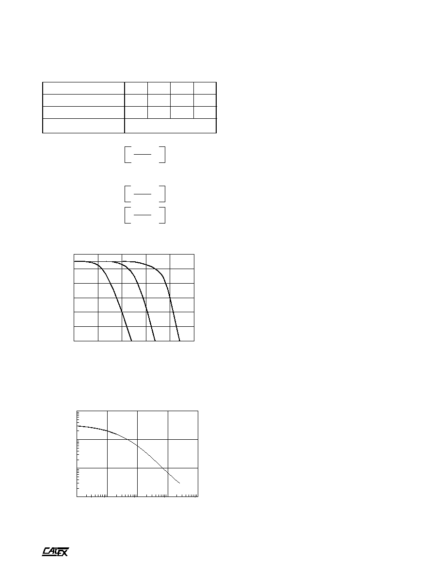
FIGURE 3.
163MK INPUT AMP RESPONSE
3 db FREQUENCY
, HERTZ
GAIN
10
0
10
1
10
2
10
3
10
4
10
6
10
5
10
4
10
3
If pin K is used as the Output Offset control, than J1 should be
installed to prevent interaction of RP1.
Filter Cutoff Frequency Adjustment
CX1 = CX2 = 0.0024 µF
-1
CUTOFF FREQUENCY > 1000 Hz
RX1 = 35,000/
-1
RX2 = 105,000/
-1
BUILT IN LOW PASS FILTER FREQUENCY RESPONSE
FREQUENCY (Hz)
GAIN (db) PIN P - PIN N
10
0
-10
-20
-30
-40
-50
1
10
100
1000
10000
1000000
10Hz
100Hz
1000Hz

A
2401 Stanwell Drive ∑ Concord, California 94520 ∑ Ph: 925/687-4411 or 800/542-3355 ∑ Fax: 925/687-3333 ∑ www.calex.com ∑ Email: sales@calex.com
5
4/2001
Model 163MK Bridgesensor
2)
Using a millivolt calibrator or the transducer output itself,
set the gain so that the proper full scale output voltage is
realized (the mV calibrator or transducer should be set to
simulate full scale output).
3)
If system offsets must be accounted for repeat step 1
again with the inputs disconnected from the source and
connected to ground, or short them together with the
bridge connected, then reconnect the inputs and re-zero
the output with the bridge balance (if used).
4)
Steps 1 - 3 above may need to be repeated several times
to achieve the desired accuracy of gain and offset.
FIGURE 6. Full Bridge with No Remote Sense
FIGURE 4. 163MK Trimpot Adjustment Detail
FIGURE 5. Full Bridge with Remote Excitation Sense
163MK Application Examples

A
2401 Stanwell Drive ∑ Concord, California 94520 ∑ Ph: 925/687-4411 or 800/542-3355 ∑ Fax: 925/687-3333 ∑ www.calex.com ∑ Email: sales@calex.com
6
4/2001
Model 163MK Bridgesensor
FIGURE 7. Half Bridge - 3 Wire
FIGURE 8. 1/4 Bridge - 2 Wire
163MK Application Examples

A
2401 Stanwell Drive ∑ Concord, California 94520 ∑ Ph: 925/687-4411 or 800/542-3355 ∑ Fax: 925/687-3333 ∑ www.calex.com ∑ Email: sales@calex.com
7
4/2001
Model 163MK Bridgesensor
FIGURE 9. 1/4 Bridge - 3 Wire
163MK Mechanical Specifications
163MK Application Examples
T
P1
B+OUT
RP2
B+ ADJUST
RP6
BRIDGE BAL
TP2
AMP OUT
RP1
OUTPUT OFFSET
RP3
INPUT OFFSET
RP5
COARSE GAIN
RP4
FINE GAIN
TP3
FIL
TERED OUTPUT
TP4
COM
J5
RG
R18
R6
RX2
RX1
ST2
ST4
ST1
ST3
J3
J4
J2
J1
CX2
CX1
1
2
3
4
5
SW1-
1
2
3
4
5
1
15
1-15
A-S
SW1
ON
OFF
FREQ
10HZ
100HZ
1KHZ
BRIDGE SUPPL
Y
10V FIXED
ADJUST
ABLE
SW2
3
4
5
ON
ON
ON
ON
ALL OFF