 | –≠–ª–µ–∫—Ç—Ä–æ–Ω–Ω—ã–π –∫–æ–º–ø–æ–Ω–µ–Ω—Ç: 178 | –°–∫–∞—á–∞—Ç—å:  PDF PDF  ZIP ZIP |
A
2401 Stanwell Drive ∑ Concord, California 94520 ∑ Ph: 925/687-4411 or 800/542-3355 ∑ Fax: 925/687-3333 ∑ www.calex.com ∑ Email: sales@calex.com
1
4/2001
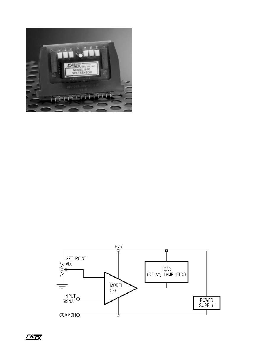
Model 540 Voltsensor
Description
The Model 540 Voltsensor is a low-cost voltage comparator in
an encapsulated, DlP-compatible package. This rugged unit
is versatile-it can be operated from a single supply of +5V to
+32V or from ±15V supplies, and the output can be connected
to sink or source current. Provision is made for optional
external adjustment of hysteresis, and the unit can be
connected for latching. The hysteresis and latching functions
are independent of the output hook-up. Whether you're driving
a relay, lighting a lamp, or driving logic circuitry, you can easily
connect the Model 540 for hysteresis or latching functions.
The combination of a high-performance IC comparator with a
versatile power-transistor output stage provides a low-cost
comparator ideally suited to industrial use. The inputs are
protected against over-voltage and the output is protected
against reverse voltage or overcurrents.
The Model 540 is easy to use. The unit is 1.4" x 0.6" x 0.5" high
with a pin configuration compatible with standard 16-pin DIP
sockets. Mounting kits are also available consisting of one or
more Model 540 Voltsensors mounted on a PC card with
various combinations of pots and relays. With the Model
MK218 Mounting Kit and two Model 540 units, high and low
set-point limits can be adjusted to provide a window
comparator for GO/NO-GO comparison.
Features
!
Rugged reliable solid state replacement for
meter relays.
!
Uses almost any power source from
+5 to +32 VDC or ±5 to ±16 VDC.
!
Withstands shock, vibration and other
environmental hazards.
!
Ignores input noise using variable dead band
(hysteresis)
!
Handles a wide variety of loads with output source
current or current sinking of 100 mA.
!
Ready to use with convenient mounting kits.
!
Easy to mount 16 pin DIP package.
Applications
The Model 540 has been designed for use in alarm, test and
control circuits. Applications well-suited for this unit are:
!
Adjustable trip point for alarm circuits
!
Process control and counting
!
Weight loading devices
!
Power supply voltage monitor
!
Production testing and quality control for
GO/NO-GO limits
In the application below, the Model 540 is connected for single
supply operation in the current-sinking mode. When the input
signal is more positive than the set-point input, a relay or lamp
load will be switched to the energized position.
Figure 1. Model 540 Connected for Single Supply Operation.
A
2401 Stanwell Drive ∑ Concord, California 94520 ∑ Ph: 925/687-4411 or 800/542-3355 ∑ Fax: 925/687-3333 ∑ www.calex.com ∑ Email: sales@calex.com
2
4/2001
Model 540 Voltsensor
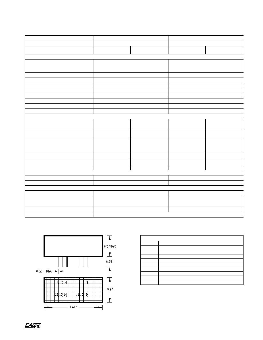
Specifications
Mechanical Specifications
Pin Assignments
n
o
i
t
a
r
e
p
O
f
o
e
d
o
M
V
2
3
+
o
t
V
5
+
V
6
1
±
o
t
V
5
±
n
o
i
t
c
e
n
n
o
C
y
l
p
p
u
S
r
e
w
o
P
V
+
(
y
l
p
p
u
S
e
l
g
n
i
S
S
)
V
±
(
y
l
p
p
u
S
l
a
u
D
S
)
n
o
i
t
c
e
n
n
o
C
t
u
p
t
u
O
-
t
n
e
r
r
u
C
e
d
o
M
g
n
i
k
n
i
S
-
t
n
e
r
r
u
C
e
d
o
M
g
n
i
c
r
u
o
S
-
t
n
e
r
r
u
C
e
d
o
M
g
n
i
k
n
i
S
-
t
n
e
r
r
u
C
e
d
o
M
g
n
i
c
r
u
o
S
t
u
p
n
I
e
g
n
a
R
t
n
i
o
P
p
i
r
T
l
e
v
e
L
y
l
p
p
u
S
.
n
i
m
t
a
l
e
v
e
L
y
l
p
p
u
S
.
x
a
m
t
a
V
0
.
3
+
o
t
V
5
.
0
+
V
0
.
0
3
+
o
t
V
5
.
0
+
V
0
.
3
+
o
t
V
5
.
4
-
V
0
.
4
1
+
o
t
V
5
.
5
1
-
y
t
il
i
b
a
t
S
t
n
i
o
P
p
i
r
T
C
∞
/
V
µ
0
4
±
C
∞
/
V
µ
0
4
±
y
t
il
i
b
a
t
a
e
p
e
R
&
y
t
i
v
i
t
i
s
n
e
S
V
m
1
V
m
1
)
s
i
s
e
r
e
t
s
y
H
(
l
a
i
t
n
e
r
e
f
f
i
D
F
F
O
/
N
O
V
+
S
.
n
i
m
,
0
0
0
1
/
V
+
S
.
n
i
m
,
0
0
0
1
/
)
1
(
e
c
n
a
d
e
p
m
I
t
u
p
n
I
m
h
o
g
e
m
1
m
h
o
g
e
m
1
e
g
a
t
l
o
V
t
u
p
n
I
.
x
a
M
V
0
0
1
±
V
0
0
1
±
t
n
e
r
r
u
C
s
a
i
B
t
u
p
n
I
A
n
0
0
5
A
n
0
0
5
t
n
e
r
r
u
C
t
e
s
f
f
O
t
u
p
n
I
A
n
0
5
A
n
0
5
e
g
a
t
l
o
V
t
e
s
f
f
O
t
u
p
n
I
V
m
0
1
±
V
m
0
1
±
t
u
p
t
u
O
e
g
a
t
l
o
V
t
u
p
t
u
O
e
t
a
t
S
h
g
i
H
V
+
S
V
+
S
V
5
.
3
-
V
+
S
V
+
S
V
5
.
3
-
e
t
a
t
S
w
o
L
.
x
a
m
V
7
.
0
+
A
m
0
0
1
+
t
a
.
x
a
m
V
m
0
5
+
.
x
a
m
V
7
.
0
+
A
m
0
0
1
+
t
a
.
x
a
m
V
m
0
5
+
e
c
n
a
d
e
p
m
I
t
u
p
t
u
O
e
t
a
t
S
h
g
i
H
h
t
i
w
r
o
t
c
e
ll
o
C
n
e
p
O
e
g
a
k
a
e
l
.
x
a
m
A
µ
1
m
h
o
0
1
h
t
i
w
r
o
t
c
e
ll
o
C
n
e
p
O
e
g
a
k
a
e
l
.
x
a
m
A
µ
1
m
h
o
0
1
e
t
a
t
S
w
o
L
r
o
t
s
i
s
n
a
r
T
.
t
a
S
.
p
m
i
.
x
a
m
m
h
o
7
m
h
o
0
1
r
o
t
s
i
s
n
a
r
T
.
t
a
S
.
p
m
i
.
x
a
m
m
h
o
7
m
h
o
0
1
g
n
i
t
a
R
t
n
e
r
r
u
C
t
u
p
t
u
O
A
m
0
0
1
+
A
m
0
0
1
+
A
m
0
0
1
+
A
m
0
0
1
+
n
o
i
t
c
e
t
o
r
P
t
n
e
r
r
u
c
r
e
v
O
A
m
0
4
1
+
A
m
0
4
1
+
A
m
0
4
1
+
A
m
0
4
1
+
e
m
i
T
e
s
n
o
p
s
e
R
e
m
i
T
g
n
i
t
a
r
e
p
O
s
µ
1
s
µ
1
e
m
i
T
ll
a
F
&
e
s
i
R
t
u
p
t
u
O
s
µ
5
2
.
0
s
µ
5
2
.
0
s
t
n
e
m
e
r
i
u
q
e
R
r
e
w
o
P
(
e
g
n
a
R
e
g
a
t
l
o
V
y
l
p
p
u
S
±V
S
)
V
2
3
+
o
t
V
5
+
V
6
1
±
o
t
V
5
±
n
i
a
r
D
t
n
e
r
r
u
C
t
n
e
c
s
e
i
u
Q
y
l
p
p
u
S
e
v
i
t
i
s
o
P
A
m
6
1
+
o
t
A
m
5
+
A
m
6
1
+
o
t
A
m
5
+
y
l
p
p
u
S
e
v
i
t
a
g
e
N
a
/
n
A
m
5
-
e
g
n
a
R
e
r
u
t
a
r
e
p
m
e
T
C
∞
0
7
+
o
t
C
∞
0
.
5
1
e
r
u
g
i
F
n
i
n
w
o
h
s
s
a
y
ll
a
n
r
e
t
x
e
d
e
t
c
e
n
n
o
c
s
i
t
o
p
s
i
s
e
r
e
t
s
y
h
e
h
t
f
i
s
l
a
n
g
i
s
t
u
p
n
i
e
v
i
t
a
g
e
n
r
o
f
m
h
o
k
0
2
1
o
t
s
p
o
r
d
t
u
p
n
i
g
n
i
t
r
e
v
n
i
-
n
o
n
o
t
n
i
e
c
n
a
d
e
p
m
I
)
1
(
BOTTOM VIEW (0.1" Grid)
s
t
n
e
m
n
g
i
s
s
A
n
i
P
1
)
g
n
i
k
n
i
S
(
T
U
P
T
U
O
2
T
U
P
T
U
O
R
O
T
A
R
A
P
M
O
C
3
s
V
+
8
T
U
P
N
I
G
N
I
T
R
E
V
N
I
9
T
U
P
N
I
G
N
I
T
R
E
V
N
I
-
N
O
N
0
1
s
V
-
1
1
T
U
P
N
I
G
N
I
H
C
T
A
L
4
1
)
d
n
a
B
d
a
e
D
(
S
I
S
E
R
E
T
S
Y
H
5
1
N
O
M
M
O
C
6
1
)
e
c
r
u
o
S
(
T
U
P
T
U
O

A
2401 Stanwell Drive ∑ Concord, California 94520 ∑ Ph: 925/687-4411 or 800/542-3355 ∑ Fax: 925/687-3333 ∑ www.calex.com ∑ Email: sales@calex.com
3
4/2001
Model 540 Voltsensor
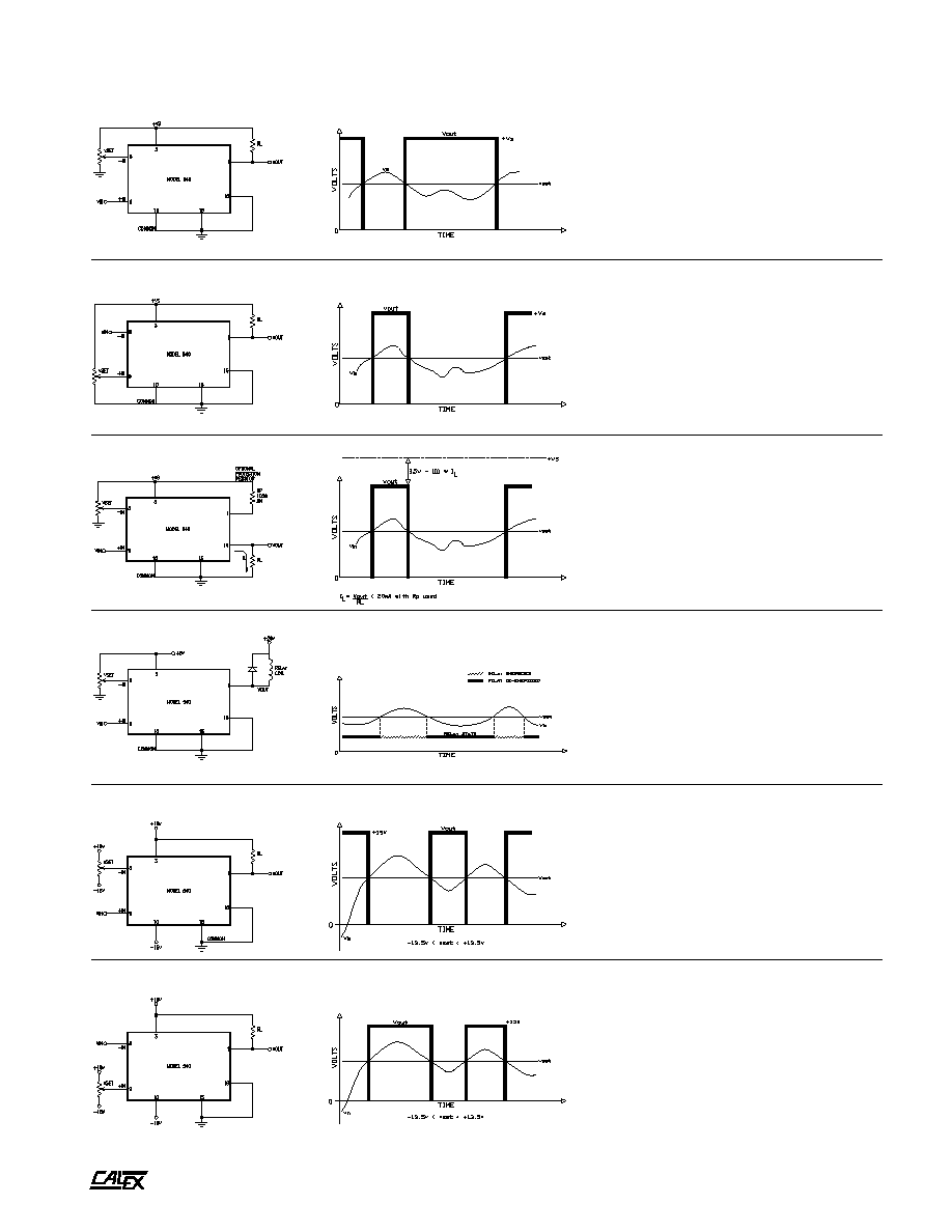
Operation
The Model 540 consists of a protected IC input stage and a
power transistor output stage. The set-point input, or
comparison voltage, can be applied to either input (pin 8 or pin
9). The varying input signal is applied to the other input. When
the voltage at pin 9 is more positive than the voltage at pin 8,
the IC comparator output switches to the high logic state and
applies a positive drive to the output power transistor Q1.
When the voltage at pin 9 is negative with respect to the
voltage at pin 8, the IC comparator will switch to the low logic
state, which is near zero volts. If the output is connected as a
current sink, (pin 16 connected to common and the load
connected between pin 1 and a positive voltage), then positive
drive from the output of the IC comparator will cause Q1 to
saturate. With Q1 switched on, the output sink can accept up
to +100 mA. A relay or lamp load at the output will be switched
to the energized condition when Q1 saturates. When the IC
comparator goes to the low state, Q1 is cut off and no current
will flow. The Voltsensor output will then rise to the positive
FIGURE 3.
FIGURE 2.
supply lead. A relay or lamp load would then be de-energized.
If the output is connected as a current source (pin 1 connected
to +V
S
and the output load connected between pin 16 and
common), then positive drive from the output of the IC
comparator will cause Q1 to go to a high output state. In this
mode of operation, Q1 is used as an emitter follower and it will
essentially follow the voltage output of the IC comparator.
When the IC comparator switches to the low state, the
Voltsensor output (output source, pin 16) will drop to nearly
zero volts (+50 mV maximum).
The input diodes protect the IC comparator for a maximum
input voltage of ±100V. The output stage is current limited to
140 mA in the event of a short circuit. The diode between
output source and common offers transient protection when
a relay is used as a load in the current-source mode.
External connections for the two modes of operation current
sinking and current sourcing, are shown below.

A
2401 Stanwell Drive ∑ Concord, California 94520 ∑ Ph: 925/687-4411 or 800/542-3355 ∑ Fax: 925/687-3333 ∑ www.calex.com ∑ Email: sales@calex.com
4
4/2001
Model 540 Voltsensor
Applications
FIGURE 6. Model 540 Connected For Current-Sourcing Mode
Figure 6 shows the connections for current-source operation.
In this mode the Model 540 is short-circuit protected for +V
S
of
+5V to +15V. If short-circuit and current limiting protection is
desired for +V
S
of +16V to +32V, a 100
2W resistor should
be connected between +Vs and pin 1. Output voltage in the
current-source mode is +V
S
- (3.5V + 10
I
L
). Figure 7 is a
graph of output voltage versus load current for current source
operation. Output leakage does not exceed 1 µA.
FIGURE 4. Model 540 Connected For Current-Sinking Mode
The connections for current-sinking operation are shown
above in Figure 4. In this mode the Model 540 is short-circuit
protected and current-limited at 140 mA. The diode across the
output transistor protects the transistor against possible back
bias. Of the two output modes, current-sinking is more desirable
because there is less power dissipation in the low output
state. When the voltage at the NON INVERTING input is more
positive than the voltage at the INVERTING input, the IC
comparator switches to the high logic state. This causes the
output transistor to saturate, which will then energize the load.
Figure 5 is a graph of output voltage versus load current for the
saturated output transistor. Output leakage does not exceed
1 µA.
0
20
40
60
80
100
LOAD CURRENT (mA)
0.00
0.20
0.40
0.60
0.80
Vo(SAT) (VDC)
OUTPUT VOLTAGE FOR CURRENT-SINKING MODE
(LOW Logic State)
0
20
40
60
80
100
LOAD CURRENT (mA)
0
5
10
15
20
25
30
OUTPUT VOLTAGE Vo (VDC)
MAXIMUM OUTPUT FOR CURRENT-SOURCING MODE
(HIGH Logic State)
Vs = 5V
Vs = 15V
Vs = 24V
Vs = 32V
FIGURE 5.
FIGURE 7.
A
2401 Stanwell Drive ∑ Concord, California 94520 ∑ Ph: 925/687-4411 or 800/542-3355 ∑ Fax: 925/687-3333 ∑ www.calex.com ∑ Email: sales@calex.com
5
4/2001
Model 540 Voltsensor
Applications
FIGURE 8.
Single Supply, Current-Sinking Mode, Resistive
Load, V
in
to +In Terminal
FIGURE 9.
Single Supply, Current-Sinking Mode, Resistive
Load, V
in
to -In Terminal
FIGURE 10.
Single Supply, Current-Sourcing Mode, Resistive
Load, V
in
to +In Terminal
FIGURE 11.
Single +5V Supply, Current-Sinking Mode, 28V
Relay as Load, V
in
to -In Terminal
FIGURE 13.
Dual Supply, Current-Sinking Mode, Resistive
Load, V
in
to -In Terminal
FIGURE 12.
Dual Supply, Current-Sinking Mode, Resistive
Load, V
in
to +In Terminal